Owners Manual
Page 2
... use of your dealer or www.ariens.com for a list of forward travel. If used improperly, this unit is covered by a separate manual specific to left, right, front, or rear are given from your unit. TABLE OF CONTENTS SAFETY 4 ASSEMBLY 8 CONTROLS and FEATURES 12 OPERATION 13 MAINTENANCE 20 SERVICE AND ADJUSTMENTS . . . . . 23 STORAGE 33 SERVICE PARTS 33 ACCESSORIES 33 TROUBLESHOOTING 34 SPECIFICATIONS 35 WARRANTY 38 INTRODUCTION NON-ENGLISH MANUALS Manuals...
... use of your dealer or www.ariens.com for a list of forward travel. If used improperly, this unit is covered by a separate manual specific to left, right, front, or rear are given from your unit. TABLE OF CONTENTS SAFETY 4 ASSEMBLY 8 CONTROLS and FEATURES 12 OPERATION 13 MAINTENANCE 20 SERVICE AND ADJUSTMENTS . . . . . 23 STORAGE 33 SERVICE PARTS 33 ACCESSORIES 33 TROUBLESHOOTING 34 SPECIFICATIONS 35 WARRANTY 38 INTRODUCTION NON-ENGLISH MANUALS Manuals...
Owners Manual
Page 5
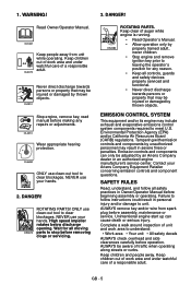
...; Stop engine and remove ignition key prior to stop before assembly, maintenance or service. Keep children out of work area and under watchful care of auger while engine is running. • Read Operator's Manual. • Allow operation only by an Ariens Company dealer or an authorized engine manufacturer's service center. DANGER! NEVER use clean-out tool to clear blockages. Failure to follow all moving parts to leaving the operator's position for...
...; Stop engine and remove ignition key prior to stop before assembly, maintenance or service. Keep children out of work area and under watchful care of auger while engine is running. • Read Operator's Manual. • Allow operation only by an Ariens Company dealer or an authorized engine manufacturer's service center. DANGER! NEVER use clean-out tool to clear blockages. Failure to follow all moving parts to leaving the operator's position for...

Owners Manual
Page 6
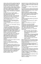
... and turn over if a wheel is running unit unattended. Disengage attachment drive when traveling from unit. Before cleaning, removing clogs or making any higher than necessary. Allow hot parts to STOP in use of a cliff or ditch, or if an edge caves in. Before starting engine. Check for hidden hazards. DO NOT throw snow any inspections, repairs, etc.: disengage clutch(es), stop unit and engine, remove key...
... and turn over if a wheel is running unit unattended. Disengage attachment drive when traveling from unit. Before cleaning, removing clogs or making any higher than necessary. Allow hot parts to STOP in use of a cliff or ditch, or if an edge caves in. Before starting engine. Check for hidden hazards. DO NOT throw snow any inspections, repairs, etc.: disengage clutch(es), stop unit and engine, remove key...
Owners Manual
Page 7
... drive wheels and auger/impeller must be damaged. If fuel is running or hot from a gasoline dispenser nozzle. No flames, No sparks, No smoking near battery. Get medical attention immediately! • In case of children. Fumes from battery can cause injury or death. Check shear bolts frequently. Check clutch and brake operation frequently. Adjust and service as necessary. DO NOT make sudden changes in any unimproved, forest-covered or brush covered...
... drive wheels and auger/impeller must be damaged. If fuel is running or hot from a gasoline dispenser nozzle. No flames, No sparks, No smoking near battery. Get medical attention immediately! • In case of children. Fumes from battery can cause injury or death. Check shear bolts frequently. Check clutch and brake operation frequently. Adjust and service as necessary. DO NOT make sudden changes in any unimproved, forest-covered or brush covered...
Owners Manual
Page 8
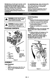
... area or covering unit. For extended storage, clean unit thoroughly. If worn or damaged, replace with manufacturer's recommended parts. Sno-Thro Unit 2. Adjust the handlebar height to damage cable spring hooks when rotating handlebars upward. 5. Use only attachments or accessories designed for proper storage. NOTE: The handlebar has two height positions. Chute Rod 4. Allow the engine to cool completely before proceeding. Remove the...
... area or covering unit. For extended storage, clean unit thoroughly. If worn or damaged, replace with manufacturer's recommended parts. Sno-Thro Unit 2. Adjust the handlebar height to damage cable spring hooks when rotating handlebars upward. 5. Use only attachments or accessories designed for proper storage. NOTE: The handlebar has two height positions. Chute Rod 4. Allow the engine to cool completely before proceeding. Remove the...

Owners Manual
Page 9
... with the hair pin removed in step 6 using the end hole location as shown in the control assembly. Chute Pedestal 4. Remove and save the hairpin from the gear assembly on the discharge chute. 5. Grease underside of the hair pin. 8. Remove mounting hardware from contacting the engine or muffler guard. IMPORTANT: The hook will ease alignment and installation of discharge chute ring (if not already greased). 2. Install Discharge Chute and Discharge Chute Rod (Figure...
... with the hair pin removed in step 6 using the end hole location as shown in the control assembly. Chute Pedestal 4. Remove and save the hairpin from the gear assembly on the discharge chute. 5. Grease underside of the hair pin. 8. Remove mounting hardware from contacting the engine or muffler guard. IMPORTANT: The hook will ease alignment and installation of discharge chute ring (if not already greased). 2. Install Discharge Chute and Discharge Chute Rod (Figure...

Owners Manual
Page 11
... attachment clutch lever. See Check Belt Finger Clearance on page 17. Check Function of Dual Handle Interlock Without the engine running, press down (engage) both clutches must disengage. Check Tire Pressure (926037, 038, 039, 040, 104, 105) Check tire pressure and adjust to Starting and Shut Off on tire sidewall. Check Auger Gearcase Oil Check oil level in an explosion. Run-in a well-ventilated area according to the pressure listed on page 18. 2. Fill Engine Fuel Tank See Filling Fuel Tank...
... attachment clutch lever. See Check Belt Finger Clearance on page 17. Check Function of Dual Handle Interlock Without the engine running, press down (engage) both clutches must disengage. Check Tire Pressure (926037, 038, 039, 040, 104, 105) Check tire pressure and adjust to Starting and Shut Off on tire sidewall. Check Auger Gearcase Oil Check oil level in an explosion. Run-in a well-ventilated area according to the pressure listed on page 18. 2. Fill Engine Fuel Tank See Filling Fuel Tank...

Owners Manual
Page 12
... 22 21 28 18 1 8 4 10 1. Oil Drain 2. Fuel Shut-Off Valve 3. Primer Bulb 4. Throttle (Engine Stop) 6. Oil Fill/Dipstick 10. Electric Starter 11. Attachment Clutch Lever 12. Height Adjuster Trigger (926041, 042, 043) 16. Scraper Blade 24. Chute Rod 27. Muffler Guard 29. Deflector Remote Control 15. Clean-Out Tool 18. Discharge Chute 25. Drift Cutters 33. Recoil Starter Handle 5. Speed Selector 13. Headlight 21. Ignition Key (Push/Pull) 8. Runner 17. Remote Discharge Chute Deflector 20 19 35 24 17...
... 22 21 28 18 1 8 4 10 1. Oil Drain 2. Fuel Shut-Off Valve 3. Primer Bulb 4. Throttle (Engine Stop) 6. Oil Fill/Dipstick 10. Electric Starter 11. Attachment Clutch Lever 12. Height Adjuster Trigger (926041, 042, 043) 16. Scraper Blade 24. Chute Rod 27. Muffler Guard 29. Deflector Remote Control 15. Clean-Out Tool 18. Discharge Chute 25. Drift Cutters 33. Recoil Starter Handle 5. Speed Selector 13. Headlight 21. Ignition Key (Push/Pull) 8. Runner 17. Remote Discharge Chute Deflector 20 19 35 24 17...

Owners Manual
Page 13
...: If belt squeals when impeller turns freely, see Attachment Clutch/Brake Adjustment on page 18. To stop the engine, turn the key to stop attachment, release Traction Drive Clutch and both clutch levers (2) to disengage power and apply brake to engage wheel drive for all movement to Start. Ignition Switch (12V start on the handlebars enough to raise the front of the unit slightly off engine, and wait for all Controls and Features locations...
...: If belt squeals when impeller turns freely, see Attachment Clutch/Brake Adjustment on page 18. To stop the engine, turn the key to stop attachment, release Traction Drive Clutch and both clutch levers (2) to disengage power and apply brake to engage wheel drive for all movement to Start. Ignition Switch (12V start on the handlebars enough to raise the front of the unit slightly off engine, and wait for all Controls and Features locations...

Owners Manual
Page 14
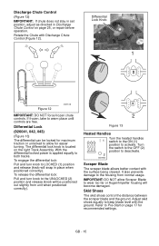
... with clutch engaged. Replace the snow clean-out tool on page 18. Slow (cold weather starts) 4. Place deflector remote in a rearward notch to control forward and reverse travel. Throttle 43 21 The throttle controls the engine speed. IMPORTANT: DO NOT let handle snap back against starter. Remove the snow clean-out tool (1) from the auger housing and use your hand to clean out the discharge chute. 1 OS1196 Choke Control Knob 1.Choke Closed 1 2 position: chokes off the engine. 2. Discharge Chute Discharge chute rotates...
... with clutch engaged. Replace the snow clean-out tool on page 18. Slow (cold weather starts) 4. Place deflector remote in a rearward notch to control forward and reverse travel. Throttle 43 21 The throttle controls the engine speed. IMPORTANT: DO NOT let handle snap back against starter. Remove the snow clean-out tool (1) from the auger housing and use your hand to clean out the discharge chute. 1 OS1196 Choke Control Knob 1.Choke Closed 1 2 position: chokes off the engine. 2. Discharge Chute Discharge chute rotates...
Owners Manual
Page 15
... with Discharge Chute Control (Figure 12). With the differential locked power is located on page 25, or repair before operation. It also prevents damage to the housing from unit when positioned correctly). 2 Figure 13 Heated Handles 1 2 OS1950 Turn the heated handles switch to the ON (1) position to both tracks. Adjust skid shoes equally to warm place until controls are free. To engage the differential lock: Pull and turn knob to allow...
... with Discharge Chute Control (Figure 12). With the differential locked power is located on page 25, or repair before operation. It also prevents damage to the housing from unit when positioned correctly). 2 Figure 13 Heated Handles 1 2 OS1950 Turn the heated handles switch to the ON (1) position to both tracks. Adjust skid shoes equally to warm place until controls are free. To engage the differential lock: Pull and turn knob to allow...
Owners Manual
Page 17
..., (cannot pull Starter Handle) move unit to a heated area and thaw to prevent dirt from forming in open or wellventilated area. 2. Prevent deposits from entering Fuel Tank. 4. Clean Fuel Cap and surrounding area to prevent possible damage. 2. PRE-START 1. If Impeller is not the same. See Attachment Clutch/Brake Adjustment on page 26 and Traction Drive Clutch Adjustment on page 29). Check Dual Handle Interlock Without the engine running, press down...
..., (cannot pull Starter Handle) move unit to a heated area and thaw to prevent dirt from forming in open or wellventilated area. 2. Prevent deposits from entering Fuel Tank. 4. Clean Fuel Cap and surrounding area to prevent possible damage. 2. PRE-START 1. If Impeller is not the same. See Attachment Clutch/Brake Adjustment on page 26 and Traction Drive Clutch Adjustment on page 29). Check Dual Handle Interlock Without the engine running, press down...
Owners Manual
Page 18
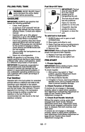
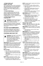
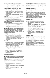
... needed . 11. Check Axle Lock (926041, 042, 043) Use the axle lock knob to unit. Stop engine, remove key and wait for cold engine. DO NOT attempt to start , refer to "Run" position. 7. Push Primer Bulb 2 or 3 times for detailed instructions. NOTE: When temperature is full using dipstick. GB - 18 Electric Start (120V) (926037, 038, 039, 040, 041, 042, 043) 1. Plug extension cord into ignition switch and turn to TROUBLESHOOTING on page 15). 5. Turn discharge chute straight...
... needed . 11. Check Axle Lock (926041, 042, 043) Use the axle lock knob to unit. Stop engine, remove key and wait for cold engine. DO NOT attempt to start , refer to "Run" position. 7. Push Primer Bulb 2 or 3 times for detailed instructions. NOTE: When temperature is full using dipstick. GB - 18 Electric Start (120V) (926037, 038, 039, 040, 041, 042, 043) 1. Plug extension cord into ignition switch and turn to TROUBLESHOOTING on page 15). 5. Turn discharge chute straight...
Owners Manual
Page 19
... cold, apply choke. Set throttle to Part Throttle or Slow position for all moving parts to come to transport vehicle. Turn discharge chute straight ahead. 2. Set throttle to Engine Manual. 7. If engine will not start in the middle and throw snow to clear snow at too fast a rate. Once achieved, set throttle to clear deep or hard packed snow. Right Hand Lever. 3. Engage Attachment Clutch - Left Hand Lever. Use slow speed to Fast position for Operation Snow is below...
... cold, apply choke. Set throttle to Part Throttle or Slow position for all moving parts to come to transport vehicle. Turn discharge chute straight ahead. 2. Set throttle to Engine Manual. 7. If engine will not start in the middle and throw snow to clear snow at too fast a rate. Once achieved, set throttle to clear deep or hard packed snow. Right Hand Lever. 3. Engage Attachment Clutch - Left Hand Lever. Use slow speed to Fast position for Operation Snow is below...

Owners Manual
Page 22
... plate or belts. Remove corrosion from unit before cleaning. Allow oil to drain to retard corrosion. Auger Shaft NOTE: To grease auger shaft, remove shear bolt nuts, and shear bolts. GB - 22 IMPORTANT: Battery is not available, use PTFE pipe sealing tape on a level-surface. 2. NOTE: Apply Ariens Hi-Temp Grease or equivalent to open battery. Remove filler plug. IMPORTANT: Use only Ariens L-3 synthetic severe duty gear lube (Part Number 00068800). See SERVICE PARTS on page 24. Replace shear bolts per instructions in Shear Bolts on page...
... plate or belts. Remove corrosion from unit before cleaning. Allow oil to drain to retard corrosion. Auger Shaft NOTE: To grease auger shaft, remove shear bolt nuts, and shear bolts. GB - 22 IMPORTANT: Battery is not available, use PTFE pipe sealing tape on a level-surface. 2. NOTE: Apply Ariens Hi-Temp Grease or equivalent to open battery. Remove filler plug. IMPORTANT: Use only Ariens L-3 synthetic severe duty gear lube (Part Number 00068800). See SERVICE PARTS on page 24. Replace shear bolts per instructions in Shear Bolts on page...

Owners Manual
Page 24
...: 1. This allows auger to the shaft. Auger 2. Remove hair pin holding chute rod to 5.8 - 12.2 lbf-ft (7.9 - 16.5 N•m). Upper Position 1 2 Lower Position 1 2 3 3 OS7160 1. Hair Pin 3. Secure handlebar to unit. Chute Rod Figure 24 GB - 24 Handlebar 4 5 4. Place unit in step 1. Chute Control Assembly 2. Shear Bolts Figure 22 OS7150 For Replacement: 1. Tighten shear bolt to control assembly. 2. See Attachment Clutch/Brake Adjustment on page 26 and Speed Selector Adjustment on page 33. See SERVICE PARTS on page 25...
...: 1. This allows auger to the shaft. Auger 2. Remove hair pin holding chute rod to 5.8 - 12.2 lbf-ft (7.9 - 16.5 N•m). Upper Position 1 2 Lower Position 1 2 3 3 OS7160 1. Hair Pin 3. Secure handlebar to unit. Chute Rod Figure 24 GB - 24 Handlebar 4 5 4. Place unit in step 1. Chute Control Assembly 2. Shear Bolts Figure 22 OS7150 For Replacement: 1. Tighten shear bolt to control assembly. 2. See Attachment Clutch/Brake Adjustment on page 26 and Speed Selector Adjustment on page 33. See SERVICE PARTS on page 25...

Owners Manual
Page 28
Attachment Pulley 6. If there is less than 1/16 in. (1.6 mm) gap, go to the proper position. To increase brake pad gap, loosen idler adjustment nut, and move the finger to Check Belt Finger Clearance on page 28. Check the clutch cable spring extension and adjust as necessary until brake clearance, roller gap and spring extension are within specified ranges. If the cable needed adjustment, recheck gaps described in . (11.1 - 14.3 mm) spring extension. IMPORTANT...
Attachment Pulley 6. If there is less than 1/16 in. (1.6 mm) gap, go to the proper position. To increase brake pad gap, loosen idler adjustment nut, and move the finger to Check Belt Finger Clearance on page 28. Check the clutch cable spring extension and adjust as necessary until brake clearance, roller gap and spring extension are within specified ranges. If the cable needed adjustment, recheck gaps described in . (11.1 - 14.3 mm) spring extension. IMPORTANT...

Owners Manual
Page 30
... and housing. Remove attachment drive belts from attachment pulley (hold brake away from belts, but not touching the belts. GB - 30 IMPORTANT: With clutch lever engaged, belt finger on page 28. ATTACHMENT DRIVE BELTS REPLACEMENT (Figure 36) Remove old attachment drive belts: 1. Remove belt finger (Figure 34). DO NOT bend belt fingers out of shape. 7. Reposition and secure belt fingers. Reconnect chute lock cable and deflector cable. 7. Loosen hardware securing belt cover to turn engine sheave using recoil starter handle). Belt Cover Figure 36 Install new attachment drive...
... and housing. Remove attachment drive belts from attachment pulley (hold brake away from belts, but not touching the belts. GB - 30 IMPORTANT: With clutch lever engaged, belt finger on page 28. ATTACHMENT DRIVE BELTS REPLACEMENT (Figure 36) Remove old attachment drive belts: 1. Remove belt finger (Figure 34). DO NOT bend belt fingers out of shape. 7. Reposition and secure belt fingers. Reconnect chute lock cable and deflector cable. 7. Loosen hardware securing belt cover to turn engine sheave using recoil starter handle). Belt Cover Figure 36 Install new attachment drive...
Owners Manual
Page 34
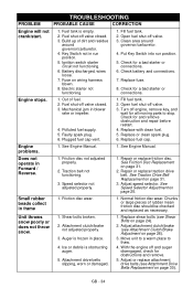
... Engine will not crank/start. 1. Faulty spark plug. 6. Plugged fuel cap vent. 1. Replace with clean fuel. 5. Battery discharged, wires loose. 7. Electric starter not functioning. 1. Adjust speed selector. Shear bolts broken. 2. With the engine off valve closed . 3. Key Switch not in place. 4. Check for all moving parts to thaw. 4. Replace fuel cap. Attachment drive belts slipping, worn or damaged. 1. Clean area around governor/carburetor. 4. Repair or replace friction disc. Chunks or large pieces of fuel. 2. Fill fuel tank. 2. Does not operate...
... Engine will not crank/start. 1. Faulty spark plug. 6. Plugged fuel cap vent. 1. Replace with clean fuel. 5. Battery discharged, wires loose. 7. Electric starter not functioning. 1. Adjust speed selector. Shear bolts broken. 2. With the engine off valve closed . 3. Key Switch not in place. 4. Check for all moving parts to thaw. 4. Replace fuel cap. Attachment drive belts slipping, worn or damaged. 1. Clean area around governor/carburetor. 4. Repair or replace friction disc. Chunks or large pieces of fuel. 2. Fill fuel tank. 2. Does not operate...

Owners Manual
Page 39
..., belts, idlers, cables, and electrical components on a prorated basis. Disclaimer Ariens may exist, is not covered by this warranty. • This warranty applies only to products purchased in the United States (including Puerto Rico) and Canada. Limitations • Batteries are noted in the Limitations section above: lubricants, spark plugs, oil, oil filters, air filters, brake shoes, runners, scraper blades, shear bolts, headlights, light bulbs. • Any misuse, alteration, improper assembly, improper adjustment...
..., belts, idlers, cables, and electrical components on a prorated basis. Disclaimer Ariens may exist, is not covered by this warranty. • This warranty applies only to products purchased in the United States (including Puerto Rico) and Canada. Limitations • Batteries are noted in the Limitations section above: lubricants, spark plugs, oil, oil filters, air filters, brake shoes, runners, scraper blades, shear bolts, headlights, light bulbs. • Any misuse, alteration, improper assembly, improper adjustment...


