Owners Manual
Page 2
... operation of your unit during normal operation and maintenance. TABLE OF CONTENTS Safety 4 Assembly 8 Controls & Features 9 Operation 10 Storage 14 Maintenance 15 Service & Adjustments 18 Troubleshooting 26 Specifications 27 Service Parts 27 Warranty 28 INTRODUCTION NON-ENGLISH MANUALS Manuals in languages other than English may be dangerous and cause personal injury or property damage. Visit your dealer or www.ariens.com for a list of languages available for the safe use...
... operation of your unit during normal operation and maintenance. TABLE OF CONTENTS Safety 4 Assembly 8 Controls & Features 9 Operation 10 Storage 14 Maintenance 15 Service & Adjustments 18 Troubleshooting 26 Specifications 27 Service Parts 27 Warranty 28 INTRODUCTION NON-ENGLISH MANUALS Manuals in languages other than English may be dangerous and cause personal injury or property damage. Visit your dealer or www.ariens.com for a list of languages available for the safe use...

Owners Manual
Page 3
... Customer Note: If you do not understand or have purchased this manual. Review control functions and operation of purchase. Review recommended lubrication, maintenance and adjustments. 5. Review Limited Warranty Policy. 6. Equipment described within this unit with the latest service information. If you with anything other than an Ariens authorized replacement part may not be optional. Fill out Original Purchaser Registration Card and return the...
... Customer Note: If you do not understand or have purchased this manual. Review control functions and operation of purchase. Review recommended lubrication, maintenance and adjustments. 5. Review Limited Warranty Policy. 6. Equipment described within this unit with the latest service information. If you with anything other than an Ariens authorized replacement part may not be optional. Fill out Original Purchaser Registration Card and return the...
Owners Manual
Page 5
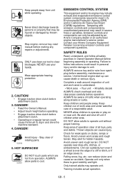
... Owner's Manual. • Adjust brush height before operating. • Engage traction drive clutch before attachment clutch. • Operating on irregular terrain could result in personal injury and/or damage to dig in Owner/Operator Manual before beginning assembly or operating. Stay clear of a responsible adult. HOT SURFACES! OL1801 EMISSION CONTROL SYSTEM This equipment and/or its engine may result in . Environmental Protection Agency (EPA) and/or California Air...
... Owner's Manual. • Adjust brush height before operating. • Engage traction drive clutch before attachment clutch. • Operating on irregular terrain could result in personal injury and/or damage to dig in Owner/Operator Manual before beginning assembly or operating. Stay clear of a responsible adult. HOT SURFACES! OL1801 EMISSION CONTROL SYSTEM This equipment and/or its engine may result in . Environmental Protection Agency (EPA) and/or California Air...
Owners Manual
Page 6
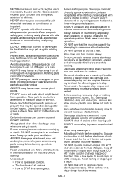
... hands or any moving parts to STOP in the manual and on a slope. Walk, never run engine in use . Do not operate in reverse or leaving the operator's position. Engage traction drive clutch before restart. Immediately stop . Remove wire from all controls. • How to stop before leaving operator's position. Protect eyes, face and head from engine exhaust can drive machine rearward. Avoid starting . Keep all times. Always provide good...
... hands or any moving parts to STOP in the manual and on a slope. Walk, never run engine in use . Do not operate in reverse or leaving the operator's position. Engage traction drive clutch before restart. Immediately stop . Remove wire from all controls. • How to stop before leaving operator's position. Protect eyes, face and head from engine exhaust can drive machine rearward. Avoid starting . Keep all times. Always provide good...
Owners Manual
Page 7
.... Adjust brush height before storing in fuel tank, inside a vehicle or on the ground. Always provide good ventilation. NEVER secure from operation. Handle with manufacturer's recommended parts. NEVER fill fuel tank when engine is not possible, then refuel such equipment on clothing, change engine governor settings or over during maintenance. If this is running . GB - 7 ALWAYS allow engine to cool before servicing. Check components frequently. DO NOT use a nozzle...
.... Adjust brush height before storing in fuel tank, inside a vehicle or on the ground. Always provide good ventilation. NEVER secure from operation. Handle with manufacturer's recommended parts. NEVER fill fuel tank when engine is not possible, then refuel such equipment on clothing, change engine governor settings or over during maintenance. If this is running . GB - 7 ALWAYS allow engine to cool before servicing. Check components frequently. DO NOT use a nozzle...

Owners Manual
Page 8
...; Do not weld or heat a wheel and tire assembly. See Attachment Drive Belt Replacement on the handlebar assembly and shift rod. . 2 1 3 4 1. Unfold Handlebar (Figure 3) 1. Explosive separation of all moving parts to Engine Manual for about 15 minutes. 3. Fill Engine Fuel Tank Refer to stop, and remove spark plug wire. 4. Refer to damage cable spring hooks when rotating handlebars upward. 5. Engage attachment clutch lever and run attachment for proper type and capacity. Shift Rod Hardware 4. Heat can...
...; Do not weld or heat a wheel and tire assembly. See Attachment Drive Belt Replacement on the handlebar assembly and shift rod. . 2 1 3 4 1. Unfold Handlebar (Figure 3) 1. Explosive separation of all moving parts to Engine Manual for about 15 minutes. 3. Fill Engine Fuel Tank Refer to stop, and remove spark plug wire. 4. Refer to damage cable spring hooks when rotating handlebars upward. 5. Engage attachment clutch lever and run attachment for proper type and capacity. Shift Rod Hardware 4. Heat can...
Owners Manual
Page 10
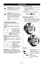
...1 Release clutch lever (2) to disengage power OL2691 and apply brake to stop movement. Set the engine shut off a running engine. 1 2 Throttle 1 2 3 The Throttle controls the engine speed. Choke Closed position: chokes off engine, and wait for propelling unit. Part-Throttle 3. Choke Control Knob 1. Keep hands and feet away from brush. Release lever (2) to : 1. To increase or decrease the engine speed, adjust to OL2701 stop before unclogging or working on snow brush. Choke Open position: allows for easier start and operate the engine. 2. Traction Drive Clutch...
...1 Release clutch lever (2) to disengage power OL2691 and apply brake to stop movement. Set the engine shut off a running engine. 1 2 Throttle 1 2 3 The Throttle controls the engine speed. Choke Closed position: chokes off engine, and wait for propelling unit. Part-Throttle 3. Choke Control Knob 1. Keep hands and feet away from brush. Release lever (2) to : 1. To increase or decrease the engine speed, adjust to OL2701 stop before unclogging or working on snow brush. Choke Open position: allows for easier start and operate the engine. 2. Traction Drive Clutch...
Owners Manual
Page 11
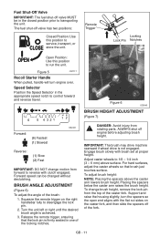
... valve has two positions: Closed Position: Use this position to 1/8 - 1/4 inch (3 - 6 mm) above the caster arm lowers brush height. Engage brush slowly with clutch engaged. To adjust brush height: NOTE: Placing the spacers above surface. Support and raise the housing slightly, turn engine over. The fuel shut-off engine before adjusting brush height. Forward speed can be in the closed position prior to service, transport, or store the unit. IMPORTANT: The brush may drive...
... valve has two positions: Closed Position: Use this position to 1/8 - 1/4 inch (3 - 6 mm) above the caster arm lowers brush height. Engage brush slowly with clutch engaged. To adjust brush height: NOTE: Placing the spacers above surface. Support and raise the housing slightly, turn engine over. The fuel shut-off engine before adjusting brush height. Forward speed can be in the closed position prior to service, transport, or store the unit. IMPORTANT: The brush may drive...

Owners Manual
Page 12
... serious injury. High altitude use a gasoline with the fuel supplier. ALWAYS clean up to use different fuels. • Never mix oil and gasoline. To add fuel to prevent dirt from the bottom of any undesirable operating problems occur, use may void the engine warranty. Install spacers on the wheel spindle above may require a different octane. NO Smoking! Remove cap. Remove the spacers from entering the fuel tank. 4. WARNING: FLAMMABLE FUEL and its...
... serious injury. High altitude use a gasoline with the fuel supplier. ALWAYS clean up to use different fuels. • Never mix oil and gasoline. To add fuel to prevent dirt from the bottom of any undesirable operating problems occur, use may void the engine warranty. Install spacers on the wheel spindle above may require a different octane. NO Smoking! Remove cap. Remove the spacers from entering the fuel tank. 4. WARNING: FLAMMABLE FUEL and its...
Owners Manual
Page 13
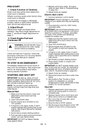
... a complete stop before operating. Adjust Brush Adjust brush height and angle before proceeding. Check and add fuel if required. NOTE: Try out each control without the engine running engine. Make sure that the traction clutch and attachment drive clutch levers are fully disengaged. 2. Set throttle to proper starting position. 6. Repeat until engine starts. IMPORTANT: Prevent damage to starter. Plug extension cord into 120V 3-wire, grounded outlet. If engine is cold, apply choke. Adjust choke as suitable for detailed instructions. 5. Run unit a few...
... a complete stop before operating. Adjust Brush Adjust brush height and angle before proceeding. Check and add fuel if required. NOTE: Try out each control without the engine running engine. Make sure that the traction clutch and attachment drive clutch levers are fully disengaged. 2. Set throttle to proper starting position. 6. Repeat until engine starts. IMPORTANT: Prevent damage to starter. Plug extension cord into 120V 3-wire, grounded outlet. If engine is cold, apply choke. Adjust choke as suitable for detailed instructions. 5. Run unit a few...
Owners Manual
Page 14
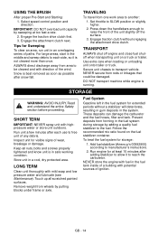
... wheels by sweeping at least 10 minutes after snow fall. Tips for extended periods without engaging the attachment drive clutch. SHORT TERM IMPORTANT: NEVER spray unit with direction of ignition. USING THE BRUSH After proper Pre-Start and Starting: 1. Prevent deposits from one work area to reach the carburetor. Fuel System Gasoline left in the fuel system for Sweeping To clear an area, run...
... wheels by sweeping at least 10 minutes after snow fall. Tips for extended periods without engaging the attachment drive clutch. SHORT TERM IMPORTANT: NEVER spray unit with direction of ignition. USING THE BRUSH After proper Pre-Start and Starting: 1. Prevent deposits from one work area to reach the carburetor. Fuel System Gasoline left in the fuel system for Sweeping To clear an area, run...
Owners Manual
Page 15
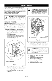
... remove key and/or wire from attachment pulley. 10. Read and understand the entire Safety section before assembly, maintenance or service. To access components in the unit frame: 1. Shut off engine and allow unit to brush assembly and detach cable (Figure 8). 1 2 1. Remove belt cover. 3. Detach cable here. Remove the bottom cover before separating unit. 5. Remove cap screws and belt finger (Figure 9). 7. Support unit frame and brush attachment. 8. Remove cap screws securing attachment to turn engine sheave using recoil starter handle). Remove attachment belt from spark plug...
... remove key and/or wire from attachment pulley. 10. Read and understand the entire Safety section before assembly, maintenance or service. To access components in the unit frame: 1. Shut off engine and allow unit to brush assembly and detach cable (Figure 8). 1 2 1. Remove belt cover. 3. Detach cable here. Remove the bottom cover before separating unit. 5. Remove cap screws and belt finger (Figure 9). 7. Support unit frame and brush attachment. 8. Remove cap screws securing attachment to turn engine sheave using recoil starter handle). Remove attachment belt from spark plug...

Owners Manual
Page 16
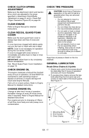
...Fasteners Check Clutch • Operation Check Clutch Spring Adjustments *• Clean Engine • Clean Recoil • Guard Foam Cover Check Engine • Oil Change Engine Oil ** • Check Tire • Pressure General Lubrication *** • • * After first five hours of operation. ** After first two hours of operation. *** Oil chains and u-joint friction areas after first 5 hours of operation and every 25 hours thereafter. Cable Attaching Hardware 3. 2 1 -A- 3 4 1. CHECK CLUTCH OPERATION Brush must stop quickly when attachment clutch lever...
...Fasteners Check Clutch • Operation Check Clutch Spring Adjustments *• Clean Engine • Clean Recoil • Guard Foam Cover Check Engine • Oil Change Engine Oil ** • Check Tire • Pressure General Lubrication *** • • * After first five hours of operation. ** After first two hours of operation. *** Oil chains and u-joint friction areas after first 5 hours of operation and every 25 hours thereafter. Cable Attaching Hardware 3. 2 1 -A- 3 4 1. CHECK CLUTCH OPERATION Brush must stop quickly when attachment clutch lever...
Owners Manual
Page 17
... Attachment Clutch/Brake Adjustment on page 21 and in safe operating range on each side of operation. Explosive separation of snow and debris. To access drive chains remove the two bolts attaching the front and rear end covers on dipstick at pressure listed on page 18. See Figure 11. 2 1 3 2 3 1. If cover is always kept clean and free of tire and rim parts is not necessary for detailed instructions. Oil level MUST be checked...
... Attachment Clutch/Brake Adjustment on page 21 and in safe operating range on each side of operation. Explosive separation of snow and debris. To access drive chains remove the two bolts attaching the front and rear end covers on dipstick at pressure listed on page 18. See Figure 11. 2 1 3 2 3 1. If cover is always kept clean and free of tire and rim parts is not necessary for detailed instructions. Oil level MUST be checked...
Owners Manual
Page 20
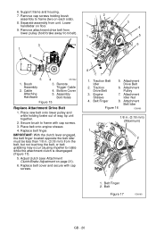
...causing impeller to rotate while the attachment clutch is disengaged (Figure 17). 5. Brush Assembly 2. Adjust clutch (see Attachment Clutch/Brake Adjustment on floor. 9. Belt Figure 17 OS8165 GB - 20 Cable Attaching Hardware 3. Remote Trigger Cable 4. Assembly Bolt Holes Figure 15 Replace Attachment Drive Belt 1. Replace belt finger. Traction 6. Place new belt onto lower pulley and while holding brush 2 assembly to frame with cap screws. 8 7 1. IMPORTANT: With the clutch lever engaged, the belt finger located opposite the belt idler must be less than 1/8 in...
...causing impeller to rotate while the attachment clutch is disengaged (Figure 17). 5. Brush Assembly 2. Adjust clutch (see Attachment Clutch/Brake Adjustment on floor. 9. Belt Figure 17 OS8165 GB - 20 Cable Attaching Hardware 3. Remote Trigger Cable 4. Assembly Bolt Holes Figure 15 Replace Attachment Drive Belt 1. Replace belt finger. Traction 6. Place new belt onto lower pulley and while holding brush 2 assembly to frame with cap screws. 8 7 1. IMPORTANT: With the clutch lever engaged, the belt finger located opposite the belt idler must be less than 1/8 in...

Owners Manual
Page 21
...be run with the belt cover off. TRACTION DRIVE BELT REPLACEMENT NOTE: Brush assembly and frame must be separated and attachment drive belt removed from idler, crankshaft pulley and driven pulley (it may be necessary to turn crankshaft pulley using recoil starter handle). 3. Remove attachment drive belt (See Remove Attachment Drive Belt on page 20). See Figure 18. 1 2 3 1. Drive Plate Figure 18 OS8170 3 2 1. Swing Gate 1 2. Pull idler away from traction drive belt and remove belt from engine sheave in frame. Replace attachment drive belt (See Replace Attachment Drive...
...be run with the belt cover off. TRACTION DRIVE BELT REPLACEMENT NOTE: Brush assembly and frame must be separated and attachment drive belt removed from idler, crankshaft pulley and driven pulley (it may be necessary to turn crankshaft pulley using recoil starter handle). 3. Remove attachment drive belt (See Remove Attachment Drive Belt on page 20). See Figure 18. 1 2 3 1. Drive Plate Figure 18 OS8170 3 2 1. Swing Gate 1 2. Pull idler away from traction drive belt and remove belt from engine sheave in frame. Replace attachment drive belt (See Replace Attachment Drive...

Owners Manual
Page 24
... DRIVE CLUTCH ADJUSTMENT If drive slips, adjust traction clutch to the proper position. Without engine running, push unit forward while slowly moving the traction drive clutch lever toward the handlebar. 3. Measure distance between the belt and the belt finger. Traction Clutch Lever 7 - 7-1/2 in first forward speed. 2. With the traction drive clutch lever disengaged, loosen the jam nut on the cable adjuster. Check traction clutch lever distance and repeat adjustment steps if necessary. 3. Adjustment Clutch Cable Pivot Pin 2. Speed Barrel Selector Arm 3. Attachment Clutch...
... DRIVE CLUTCH ADJUSTMENT If drive slips, adjust traction clutch to the proper position. Without engine running, push unit forward while slowly moving the traction drive clutch lever toward the handlebar. 3. Measure distance between the belt and the belt finger. Traction Clutch Lever 7 - 7-1/2 in first forward speed. 2. With the traction drive clutch lever disengaged, loosen the jam nut on the cable adjuster. Check traction clutch lever distance and repeat adjustment steps if necessary. 3. Adjustment Clutch Cable Pivot Pin 2. Speed Barrel Selector Arm 3. Attachment Clutch...

Owners Manual
Page 26
... and remove obstruction and repair before restart. 3. Check for all moving parts to stop. Replace with clean fuel. 4. Repair or replace traction drive belt. See Service and Adjustments on engine shut off valve. 3. Lubricate casters. GB - 26 Engine stops. Engine problems. Does not operate in brush. 3. Fuel shut-off . 4. Engine shut off switch turned off valve closed. 3. Faulty spark plug. 1. See Engine Manual. 1. Friction disc wear. 1. Lubricate u-joint. 2. Out of rubber mean friction disc should be checked and replaced as expected TROUBLESHOOTING...
... and remove obstruction and repair before restart. 3. Check for all moving parts to stop. Replace with clean fuel. 4. Repair or replace traction drive belt. See Service and Adjustments on engine shut off valve. 3. Lubricate casters. GB - 26 Engine stops. Engine problems. Does not operate in brush. 3. Fuel shut-off . 4. Engine shut off switch turned off valve closed. 3. Faulty spark plug. 1. See Engine Manual. 1. Friction disc wear. 1. Lubricate u-joint. 2. Out of rubber mean friction disc should be checked and replaced as expected TROUBLESHOOTING...
Owners Manual
Page 28
... Gravely dealer will repair any defect in the literature package and return it to the Ariens Company, or register the unit online at the time of purchase. Two-Year Limited Lawn and Garden Warranty This warranty statement applies only to 21-Inch Walk Behind Lawn Mowers, Wide Area Walks, AMP Wide Area Walks, Tillers, String Trimmers, Log Splitters, Edgers and Power Brushes Ariens Company (Ariens) warrants to the...
... Gravely dealer will repair any defect in the literature package and return it to the Ariens Company, or register the unit online at the time of purchase. Two-Year Limited Lawn and Garden Warranty This warranty statement applies only to 21-Inch Walk Behind Lawn Mowers, Wide Area Walks, AMP Wide Area Walks, Tillers, String Trimmers, Log Splitters, Edgers and Power Brushes Ariens Company (Ariens) warrants to the...
Owners Manual
Page 29
..., on how long an implied warranty lasts, so the above : lubricants, spark plugs, oil, oil filters, air filters, fuel filters, brake linings, brake arms, brake shoes, runners, scraper blades, shear bolts, mower blades, mower vanes, tines, brushes, headlights, light bulbs, knives, cutters. • Any misuse, alteration, improper assembly, improper adjustment, neglect, or accident which vary from time to the battery packs on AMP series products. To find an Ariens or Gravely authorized service representative, contact Ariens at: 655 W. Ryan Street...
..., on how long an implied warranty lasts, so the above : lubricants, spark plugs, oil, oil filters, air filters, fuel filters, brake linings, brake arms, brake shoes, runners, scraper blades, shear bolts, mower blades, mower vanes, tines, brushes, headlights, light bulbs, knives, cutters. • Any misuse, alteration, improper assembly, improper adjustment, neglect, or accident which vary from time to the battery packs on AMP series products. To find an Ariens or Gravely authorized service representative, contact Ariens at: 655 W. Ryan Street...


