User Guide
Page 4
... the Server Has a Problem 46 What to Do If . . . 47 5 Installing or Replacing Server Components 49 Installing or Replacing an Apple Drive Module 50 Opening and Closing the Server 52 Adding Memory 56 Installing a PCI Card 59 About PCI Cards for the Server 59 Install a PCI Card in a Long Card Slot 60 Install a PCI Card in the PCI/AGP Card Slot 64 Replacing the Battery 67 Appendix A Specifications 69 Processor and Memory Specifications 69 Dimensions and Operating Environment 69 CD-ROM Specifications 70 Ethernet...
... the Server Has a Problem 46 What to Do If . . . 47 5 Installing or Replacing Server Components 49 Installing or Replacing an Apple Drive Module 50 Opening and Closing the Server 52 Adding Memory 56 Installing a PCI Card 59 About PCI Cards for the Server 59 Install a PCI Card in a Long Card Slot 60 Install a PCI Card in the PCI/AGP Card Slot 64 Replacing the Battery 67 Appendix A Specifications 69 Processor and Memory Specifications 69 Dimensions and Operating Environment 69 CD-ROM Specifications 70 Ethernet...
User Guide
Page 7
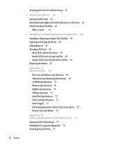
... CD-ROM drive; two USB ports; and VGA monitor connection m cable-management arm to allow the unit to four hot-pluggable ATA 100 hard disks, accessible from the front to exchange or add components. This product is installed in a rack. power and system identifier buttons and lights; Once the server is designed to be opened without disconnecting cables m two internal expansion slots for PCI cards and one or two G4 processors with minimum operating speed...
... CD-ROM drive; two USB ports; and VGA monitor connection m cable-management arm to allow the unit to four hot-pluggable ATA 100 hard disks, accessible from the front to exchange or add components. This product is installed in a rack. power and system identifier buttons and lights; Once the server is designed to be opened without disconnecting cables m two internal expansion slots for PCI cards and one or two G4 processors with minimum operating speed...
User Guide
Page 11
...;er light turns on if a problem is turned on the back panel. The upper light represents a network card; In a server with the server. C CD drive Open button When the server is detected. It also can be removed and installed while the server is useful for more information.) Each drive module has lights showing operating status and disk activity. System activity lights Two rows of system activity lights operate in a dual-processor server, the rows of the server. Drive modules and lights...
...;er light turns on if a problem is turned on the back panel. The upper light represents a network card; In a server with the server. C CD drive Open button When the server is detected. It also can be removed and installed while the server is useful for more information.) Each drive module has lights showing operating status and disk activity. System activity lights Two rows of system activity lights operate in a dual-processor server, the rows of the server. Drive modules and lights...
User Guide
Page 13
... slot takes a 7-inch PCI card or, in the server. (In some configurations, the card may be turned on the front panel. it stays connected when the server is on page 59 for setup or monitoring tasks. FireWire ports Connect FireWire devices to a high-speed Ethernet network. This indicator is detected. ≤ Power socket The power cord connects here; The AGP card requires a special adapter. ™ VGA monitor port Connect a VGA monitor to connect peripheral devices. It also can install...
... slot takes a 7-inch PCI card or, in the server. (In some configurations, the card may be turned on the front panel. it stays connected when the server is on page 59 for setup or monitoring tasks. FireWire ports Connect FireWire devices to a high-speed Ethernet network. This indicator is detected. ≤ Power socket The power cord connects here; The AGP card requires a special adapter. ™ VGA monitor port Connect a VGA monitor to connect peripheral devices. It also can install...

User Guide
Page 23
... 3 Installing Your Server in several types of racks, including m open four-post rack, 19 inches wide and 29-36 inches deep m cabinet with four-post rack inside . The brackets and screws necessary to attach the server to any of these standards. It is not designed for Xserve should meet the specifications of the server as a desktop machine. Any...
... 3 Installing Your Server in several types of racks, including m open four-post rack, 19 inches wide and 29-36 inches deep m cabinet with four-post rack inside . The brackets and screws necessary to attach the server to any of these standards. It is not designed for Xserve should meet the specifications of the server as a desktop machine. Any...

User Guide
Page 24
... the server to work with the server. m If possible, arrange to the rack. m For a two-post rack, you 'll need for installing are the same, whichever type of screws are provided with another person as well. Instructions for positioning the server in a rack. Preparations for the installation. (All except the screwdrivers are given below. m Clear a table, cart, or other set (English...
... the server to work with the server. m If possible, arrange to the rack. m For a two-post rack, you 'll need for installing are the same, whichever type of screws are provided with another person as well. Instructions for positioning the server in a rack. Preparations for the installation. (All except the screwdrivers are given below. m Clear a table, cart, or other set (English...

User Guide
Page 27
... When you slide the cover toward the back of the unit. Installing Your Server in place as you 've removed the cover, set it aside. 5 Remove the cover of the server's enclosure by sliding it toward the back. Press these two latches to release the cover from the server and remove it. 6 When the cover is almost off . With the server resting on a flat...
... When you slide the cover toward the back of the unit. Installing Your Server in place as you 've removed the cover, set it aside. 5 Remove the cover of the server's enclosure by sliding it toward the back. Press these two latches to release the cover from the server and remove it. 6 When the cover is almost off . With the server resting on a flat...

User Guide
Page 28
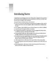
PCI card slots (2) PCI/AGP card slot RAM slots (4) 8 If necessary, install any optional internal components, such as additional memory or a PCI card, in the server. Follow the instructions in "Installing or Replacing an Apple Drive Module" on page 49. 7 If necessary, install any additional Apple Drive Modules in the front panel of the server. Drive module bay 1 Drive module bay 2 Drive module bay 3 Drive module bay 4 28 Chapter 3 Follow the appropriate instructions in Chapter 5, "Installing or Replacing Server Components," on page 50.
PCI card slots (2) PCI/AGP card slot RAM slots (4) 8 If necessary, install any optional internal components, such as additional memory or a PCI card, in the server. Follow the instructions in "Installing or Replacing an Apple Drive Module" on page 49. 7 If necessary, install any additional Apple Drive Modules in the front panel of the server. Drive module bay 1 Drive module bay 2 Drive module bay 3 Drive module bay 4 28 Chapter 3 Follow the appropriate instructions in Chapter 5, "Installing or Replacing Server Components," on page 50.
User Guide
Page 30
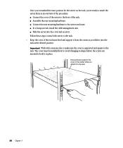
... a four-post rack, install the cable-management arm. Important Work with someone support the cover in the center while you attach it in place. m Slide the server into the cover and secure it into the rack at the desired position. Follow these steps to attach the server to the rack. The cover must be installed level to avoid changing its shape before the...
... a four-post rack, install the cable-management arm. Important Work with someone support the cover in the center while you attach it in place. m Slide the server into the cover and secure it into the rack at the desired position. Follow these steps to attach the server to the rack. The cover must be installed level to avoid changing its shape before the...

User Guide
Page 32
... side of the top cover. 3 At the back of the server, position the small bracket inside of the server (when facing the back). Note: Start on the inside the server's cover so that the curved end is near the back on the small bracket and continue to slide the brace forward a few inches. This makes installing the cable-management arm more ef...
... side of the top cover. 3 At the back of the server, position the small bracket inside of the server (when facing the back). Note: Start on the inside the server's cover so that the curved end is near the back on the small bracket and continue to slide the brace forward a few inches. This makes installing the cable-management arm more ef...

User Guide
Page 37
... to install the server in a two-post rack. (These instructions assume that you 've installed the server in the rack or cabinet, you can attach cables for details.) Installing Your Server in a Two-Post (Telco) Rack The server attaches to the floor. Important Before installing the server in a two-post rack, make certain that the front and back of connecting cables and using the cable-management...
... to install the server in a two-post rack. (These instructions assume that you 've installed the server in the rack or cabinet, you can attach cables for details.) Installing Your Server in a Two-Post (Telco) Rack The server attaches to the floor. Important Before installing the server in a two-post rack, make certain that the front and back of connecting cables and using the cable-management...

User Guide
Page 40
... ports (2) USB ports (2) Serial console port VGA monitor port 40 Chapter 3 The labels allow you can bypass the cable-management arm with the server.) 2 Attach an identifying label to each cable to its respective port. In this instance, you to locate a specific cable quickly and avoid errors when disconnecting cables. 3 Beginning at one side of the server's back panel, connect each cable you are connecting. Do not attach the power cord yet. Make...
... ports (2) USB ports (2) Serial console port VGA monitor port 40 Chapter 3 The labels allow you can bypass the cable-management arm with the server.) 2 Attach an identifying label to each cable to its respective port. In this instance, you to locate a specific cable quickly and avoid errors when disconnecting cables. 3 Beginning at one side of the server's back panel, connect each cable you are connecting. Do not attach the power cord yet. Make...

User Guide
Page 43
.... If a KVM (keyboard-video-mouse) switch is not grounded, contact a licensed electrician to insert the plug into a power source. If you are located, you can do one of the following: m Connect a monitor, keyboard, and mouse to the USB ports on page 45 for instructions. Warning This equipment is intended to set up the software. You can configure the server locally or use it. Installing Your Server in the...
.... If a KVM (keyboard-video-mouse) switch is not grounded, contact a licensed electrician to insert the plug into a power source. If you are located, you can do one of the following: m Connect a monitor, keyboard, and mouse to the USB ports on page 45 for instructions. Warning This equipment is intended to set up the software. You can configure the server locally or use it. Installing Your Server in the...

User Guide
Page 45
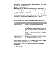
... software documentation included with your server, you can turn it on the front panel indicate network connection, system activity, and drive module use with the server. Status lights on and set up . See the Quick Start for Xserve booklet for setting up all the services and options of the server's front panel to turn it on , and the server starts up the software and network services. CHAPTER 4 Using Your Server 4 When you've connected the cables and peripheral devices...
... software documentation included with your server, you can turn it on the front panel indicate network connection, system activity, and drive module use with the server. Status lights on and set up . See the Quick Start for Xserve booklet for setting up all the services and options of the server's front panel to turn it on , and the server starts up the software and network services. CHAPTER 4 Using Your Server 4 When you've connected the cables and peripheral devices...
User Guide
Page 46
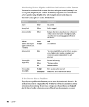
The server's status lights are listed in port; do not remove drive module If the Server Has a Problem If you can assess the situation and often solve the problem from a remote computer. see the Quick Start for Xserve booklet to consult. 46 Chapter 4 Indicator Power Security lock System identifier Ethernet (lower is a hardware error in the server or that someone has turned on the Server The server has a number of...
The server's status lights are listed in port; do not remove drive module If the Server Has a Problem If you can assess the situation and often solve the problem from a remote computer. see the Quick Start for Xserve booklet to consult. 46 Chapter 4 Indicator Power Security lock System identifier Ethernet (lower is a hardware error in the server or that someone has turned on the Server The server has a number of...
User Guide
Page 47
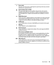
... to the Apple Support Web site for the latest troubleshooting information and software updates: www.apple.com/support Using Your Server 47 The light turns on page 50. Continue holding in the open the server and exchange components, see "Installing or Replacing an Apple Drive Module" on when the server has a problem; Close the CD tray. If you want to exchange or add a drive module, see Chapter 5, "Installing or Replacing Server Components," on server hardware. Check...
... to the Apple Support Web site for the latest troubleshooting information and software updates: www.apple.com/support Using Your Server 47 The light turns on page 50. Continue holding in the open the server and exchange components, see "Installing or Replacing an Apple Drive Module" on when the server has a problem; Close the CD tray. If you want to exchange or add a drive module, see Chapter 5, "Installing or Replacing Server Components," on server hardware. Check...

User Guide
Page 67
... be sure to unplug the power cord. Installing or Replacing Server Components 67 Make sure that the cord is installed. 1 Shut down the server. Some signs that you need to its date and time settings. Swing the small metal plate to replace the battery are intermittent problems starting up the computer and random changes in the back panel. 9 Close the card retainer on the main logic board.
... be sure to unplug the power cord. Installing or Replacing Server Components 67 Make sure that the cord is installed. 1 Shut down the server. Some signs that you need to its date and time settings. Swing the small metal plate to replace the battery are intermittent problems starting up the computer and random changes in the back panel. 9 Close the card retainer on the main logic board.
User Guide
Page 71
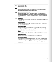
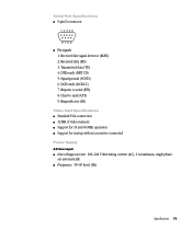
Serial Port Specifications m 9-pin D connector 12345 6789 m Pin signals 1: Received line signal detector (RLSD) 2: Received data (RD) 3: Transmitted data (TD) 4: DTE ready (DRT CD) 5: Signal ground (SGND) 6: DCE ready (DCR CC) 7: Request to send (RTS) 8: Clear to send (CTS) 9: Ring indicator (RI) Video Card Specifications m Standard VGA connection m 32 MB of video memory m Support for 33 and 66 MHz operation m Support for startup without a monitor connected Power Supply AC line input m Line voltage/current...
Serial Port Specifications m 9-pin D connector 12345 6789 m Pin signals 1: Received line signal detector (RLSD) 2: Received data (RD) 3: Transmitted data (TD) 4: DTE ready (DRT CD) 5: Signal ground (SGND) 6: DCE ready (DCR CC) 7: Request to send (RTS) 8: Clear to send (CTS) 9: Ring indicator (RI) Video Card Specifications m Standard VGA connection m 32 MB of video memory m Support for 33 and 66 MHz operation m Support for startup without a monitor connected Power Supply AC line input m Line voltage/current...
User Guide
Page 74
... got into a port. m Never force a connector into your equipment or cause an interruption in the server's operation. Depending on the server or other components. Certain components and cables-hard disks, a VGA monitor, FireWire, Ethernet, and USB devices-are installed in relation to the port. If you have to arrange for a monitor or a serial device. m Keep all ventilation openings clear and unobstructed. Failure to be installed or removed while the server is removed from direct sunlight...
... got into a port. m Never force a connector into your equipment or cause an interruption in the server's operation. Depending on the server or other components. Certain components and cables-hard disks, a VGA monitor, FireWire, Ethernet, and USB devices-are installed in relation to the port. If you have to arrange for a monitor or a serial device. m Keep all ventilation openings clear and unobstructed. Failure to be installed or removed while the server is removed from direct sunlight...

User Guide
Page 77
... is operated in a service-accessible area. The Class 1 label, located in a user-accessible area, indicates that included the use with radio communications. These limits are designed to be determined by Apple Computer, Inc., could void the EMC compliance and negate your authority to operate the product. CISPR 22 & EN55022 Statement Warning This is important that you have an internal Apple CD-ROM drive...
... is operated in a service-accessible area. The Class 1 label, located in a user-accessible area, indicates that included the use with radio communications. These limits are designed to be determined by Apple Computer, Inc., could void the EMC compliance and negate your authority to operate the product. CISPR 22 & EN55022 Statement Warning This is important that you have an internal Apple CD-ROM drive...


