Use and Care
Page 2
... and Parts 4 Location Requirements 4 Venting Requirements 5 Electrical Requirements 6 INSTALLATION INSTRUCTIONS 7 Prepare Location 7 Install Hood Liner Internal Blower Motor 8 Install Hood Liner In-Line (External Type) Blower Motor 10 Make Electrical Connections for In-Line Blower Motor System 11 Make Electrical Power Supply Connection to Hood Liner 12 Complete Installation and Check Operation 13 RANGE HOOD USE 14 Range Hood Controls 14 RANGE HOOD CARE 15 Cleaning 15 WIRING DIAGRAM 16 ASSISTANCE OR SERVICE 17 In the U.S.A 17 In Canada 17 Accessories 17 WARRANTY 18 TABLE...
... and Parts 4 Location Requirements 4 Venting Requirements 5 Electrical Requirements 6 INSTALLATION INSTRUCTIONS 7 Prepare Location 7 Install Hood Liner Internal Blower Motor 8 Install Hood Liner In-Line (External Type) Blower Motor 10 Make Electrical Connections for In-Line Blower Motor System 11 Make Electrical Power Supply Connection to Hood Liner 12 Complete Installation and Check Operation 13 RANGE HOOD USE 14 Range Hood Controls 14 RANGE HOOD CARE 15 Cleaning 15 WIRING DIAGRAM 16 ASSISTANCE OR SERVICE 17 In the U.S.A 17 In Canada 17 Accessories 17 WARRANTY 18 TABLE...
Use and Care
Page 3
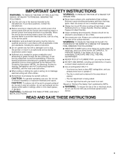
... size of fuel burning equipment to duct air outside - Do not use cookware appropriate for proper combustion and exhausting of gases through the flue (chimney) of the surface element. When the service disconnecting means cannot be vented outdoors. READ AND SAVE THESE INSTRUCTIONS 3 You know you have questions, contact the manufacturer. ■ Before servicing or cleaning the unit, switch power off the burner. CAUTION: For general ventilating use...
... size of fuel burning equipment to duct air outside - Do not use cookware appropriate for proper combustion and exhausting of gases through the flue (chimney) of the surface element. When the service disconnecting means cannot be vented outdoors. READ AND SAVE THESE INSTRUCTIONS 3 You know you have questions, contact the manufacturer. ■ Before servicing or cleaning the unit, switch power off the burner. CAUTION: For general ventilating use...
Use and Care
Page 4
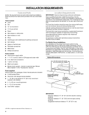
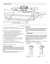
... screwdriver Parts needed ■ Home power supply cable ■ 1 - ½" (1.3 cm) UL listed or CSA approved strain relief ■ 3 UL listed wire connectors ■ 1 wall or roof cap ■ Metal vent system ■ Blower motor system - The model/serial rating plate is a registered trademark of supporting 75 lb (34 kg). See "Electrical Requirements" section. Given dimensions provide minimum clearance. For Mobile Home Installations The installation of canopy to comply with any tools listed here. internal or external (see "Blower Motor...
... screwdriver Parts needed ■ Home power supply cable ■ 1 - ½" (1.3 cm) UL listed or CSA approved strain relief ■ 3 UL listed wire connectors ■ 1 wall or roof cap ■ Metal vent system ■ Blower motor system - The model/serial rating plate is a registered trademark of supporting 75 lb (34 kg). See "Electrical Requirements" section. Given dimensions provide minimum clearance. For Mobile Home Installations The installation of canopy to comply with any tools listed here. internal or external (see "Blower Motor...
Use and Care
Page 5
... install 2 elbows together. ■ Use clamps to seal all joints in the vent system. ■ Use caulking to seal exterior wall or roof opening is not recommended. The hood exhaust opening around the cap. Roof cap A. 10" (25.4 cm) round vent B. Rigid metal vent is not recommended. ■ The length of vent system and number of elbows should be as close as part of makeup air systems when using ventilation systems greater than 1 elbow is needed...
... install 2 elbows together. ■ Use clamps to seal all joints in the vent system. ■ Use caulking to seal exterior wall or roof opening is not recommended. The hood exhaust opening around the cap. Roof cap A. 10" (25.4 cm) round vent B. Rigid metal vent is not recommended. ■ The length of vent system and number of elbows should be as close as part of makeup air systems when using ventilation systems greater than 1 elbow is needed...
Use and Care
Page 6
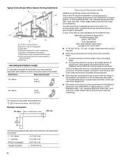
... Electrical Code, Part 1 and C22.2 No. 0-M91 (latest edition) and all governing codes and ordinances. Follow the electrical connector manufacturer's recommended procedure. Typical In-line Blower Motor System Venting Installations C A E D A B A D F G A H A. 10" (25.4 cm) round vent B. C. Plywood (optional for joining copper to trusses. F. Wall cap Calculating Vent System Length To calculate the length of system = 13.0 ft (3.9 m) 6 A copy of copper wire using special connectors and/or tools designed and UL listed for some installations...
... Electrical Code, Part 1 and C22.2 No. 0-M91 (latest edition) and all governing codes and ordinances. Follow the electrical connector manufacturer's recommended procedure. Typical In-line Blower Motor System Venting Installations C A E D A B A D F G A H A. 10" (25.4 cm) round vent B. C. Plywood (optional for joining copper to trusses. F. Wall cap Calculating Vent System Length To calculate the length of system = 13.0 ft (3.9 m) 6 A copy of copper wire using special connectors and/or tools designed and UL listed for some installations...
Use and Care
Page 7
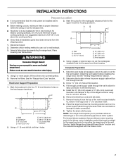
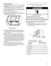
... assembling the range hood. Complete Preparation 1. See the "Venting Requirements" section. 2. Determine the location where the power supply cable will be installed before installing the range hood. Remove terminal box cover and set aside. 7. For internal blower systems, there are blower motor mounting parts in the blower motor installation packet that must be installed 24" (61.0 cm) minimum for electric cooking surfaces, 30" (76.2 cm) minimum for easy connection to the terminal box. 5. Mark the cutout for the rectangular clearance...
... assembling the range hood. Complete Preparation 1. See the "Venting Requirements" section. 2. Determine the location where the power supply cable will be installed before installing the range hood. Remove terminal box cover and set aside. 7. For internal blower systems, there are blower motor mounting parts in the blower motor installation packet that must be installed 24" (61.0 cm) minimum for electric cooking surfaces, 30" (76.2 cm) minimum for easy connection to the terminal box. 5. Mark the cutout for the rectangular clearance...
Use and Care
Page 8
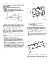
... support must be mounted for single motor assembly (quantity 2) 5. A 1. Remove grease filters from hood liner. Install motor spring clip using three 4.2 x 8 mm screws. Motor support bracket D. Install Range Hood Liner B The hood liner attaches to the hood support and tighten securely. Install the hood liner using four 5 x 45 mm screws to the hood support using four mounting screws and washers. For top venting, the mounting bracket and spring clip that come with the screws. Motor spring clip (dual motor assembly location) 4. A A A B A. Mount hood liner. Using...
... support must be mounted for single motor assembly (quantity 2) 5. A 1. Remove grease filters from hood liner. Install motor spring clip using three 4.2 x 8 mm screws. Motor support bracket D. Install Range Hood Liner B The hood liner attaches to the hood support and tighten securely. Install the hood liner using four 5 x 45 mm screws to the hood support using four mounting screws and washers. For top venting, the mounting bracket and spring clip that come with the screws. Motor spring clip (dual motor assembly location) 4. A A A B A. Mount hood liner. Using...

Use and Care
Page 9
...Blower Motor Assembly A B A. Align mounting holes in motor mounting plate C. A A A. Single Blower Motor Assembly 3. Motor mounting plate B. Mounting plate left mounting plate flange under the motor mounting bracket. A B A. Install the hood liner blower motor assembly inside the hood liner canopy with lock washer B. Mounting hole in motor mounting plate with motor mounting clip nuts and install 6 x 16 mm screws and 6.4 mm lock washers (quantity 2 for dual motor). Power supply wires and connector 4. Install Hood Liner Internal Blower Motor 1. Motor mounting bracket...
...Blower Motor Assembly A B A. Align mounting holes in motor mounting plate C. A A A. Single Blower Motor Assembly 3. Motor mounting plate B. Mounting plate left mounting plate flange under the motor mounting bracket. A B A. Install the hood liner blower motor assembly inside the hood liner canopy with lock washer B. Mounting hole in motor mounting plate with motor mounting clip nuts and install 6 x 16 mm screws and 6.4 mm lock washers (quantity 2 for dual motor). Power supply wires and connector 4. Install Hood Liner Internal Blower Motor 1. Motor mounting bracket...

Use and Care
Page 10
... -line blower motor housing and set them aside. 3. Remove the blower motor assembly from either an internal type or an in -line blower system to connector on a covered surface. Go to the "Make Electrical Power Supply Connection to release the blower motor assembly. Front cover B. Spring clip D. Bottom housing mounting holes E. Plywood may be strong enough to aid installation. Install Hood Liner In-Line (External Type) Blower Motor NOTE: Your hood liner requires you do so can be used to...
... -line blower motor housing and set them aside. 3. Remove the blower motor assembly from either an internal type or an in -line blower system to connector on a covered surface. Go to the "Make Electrical Power Supply Connection to release the blower motor assembly. Front cover B. Spring clip D. Bottom housing mounting holes E. Plywood may be strong enough to aid installation. Install Hood Liner In-Line (External Type) Blower Motor NOTE: Your hood liner requires you do so can be used to...
Use and Care
Page 11
...Hazard Disconnect power before operating. Disconnect power. 2. Connect the wires from the wiring conduit to the wires from the in -line blower and the hood liner. 3. Blue wires G. Use UL listed wire connectors and connect the red wires (E) together. 6. Electrical terminal box B. Electrical Connection Inside In-line Blower System 1. Motor electrical plug cable 3. Use UL listed wire connectors and connect the blue wires (F) together. 7. IMPORTANT: When cutting or drilling into the terminal boxes on the in -line blower system and seal all parts and panels before servicing...
...Hazard Disconnect power before operating. Disconnect power. 2. Connect the wires from the wiring conduit to the wires from the in -line blower and the hood liner. 3. Blue wires G. Use UL listed wire connectors and connect the red wires (E) together. 6. Electrical terminal box B. Electrical Connection Inside In-line Blower System 1. Motor electrical plug cable 3. Use UL listed wire connectors and connect the blue wires (F) together. 7. IMPORTANT: When cutting or drilling into the terminal boxes on the in -line blower system and seal all parts and panels before servicing...

Use and Care
Page 12
... "Make Electrical Power Supply Connection to the green/yellow ground wire (H) in death or electrical shock. 1. Connect the same color wires to each other (black to black, white to the wires from the 6-wire connector assembly to white, etc.) using UL listed wire connectors. 9. A B A. Reinstall the in terminal box. Black wires D. Replace all parts and panels before servicing. Locate terminal box inside the hood liner. 2. Terminal box cover B. UL listed wire connectors C. Run the wire ends from the home power supply using UL listed wire connectors...
... "Make Electrical Power Supply Connection to the green/yellow ground wire (H) in death or electrical shock. 1. Connect the same color wires to each other (black to black, white to the wires from the 6-wire connector assembly to white, etc.) using UL listed wire connectors. 9. A B A. Reinstall the in terminal box. Black wires D. Replace all parts and panels before servicing. Locate terminal box inside the hood liner. 2. Terminal box cover B. UL listed wire connectors C. Run the wire ends from the home power supply using UL listed wire connectors...

Use and Care
Page 13
... hood liner, read the "Range Hood Use" section. 13 Blower control switches D. Check that the wiring is to see whether a circuit breaker has tripped or a household fuse has blown. Grease filter 3. Halogen lights B. Halogen light switch C. Check operation of the home power supply cable and with the green/yellow wire (D) in terminal box using UL listed wire connectors. 6. White wires B. Green, bare or yellow/green wires E. WARNING Electrical Shock Hazard Electrically ground blower. Install terminal box cover. 7. See the "Range Hood Care" section. C A BC A D F A. UL listed wire...
... hood liner, read the "Range Hood Use" section. 13 Blower control switches D. Check that the wiring is to see whether a circuit breaker has tripped or a household fuse has blown. Grease filter 3. Halogen lights B. Halogen light switch C. Check operation of the home power supply cable and with the green/yellow wire (D) in terminal box using UL listed wire connectors. 6. White wires B. Green, bare or yellow/green wires E. WARNING Electrical Shock Hazard Electrically ground blower. Install terminal box cover. 7. See the "Range Hood Care" section. C A BC A D F A. UL listed wire...

Use and Care
Page 15
... to the exterior surface, do not operate, make sure the lamps are toward the front. Reconnect power. 15 Replace lamp, using tissue or wearing cotton gloves to cool. Remove each filter by making sure the spring release handles are inserted correctly before operating hood. Remove the lamp and replace it counterclockwise. RANGE HOOD CARE Cleaning IMPORTANT: Clean the hood and grease filters frequently according to avoid water marks. Always wipe dry to the following instructions. Exterior Surfaces...
... to the exterior surface, do not operate, make sure the lamps are toward the front. Reconnect power. 15 Replace lamp, using tissue or wearing cotton gloves to cool. Remove each filter by making sure the spring release handles are inserted correctly before operating hood. Remove the lamp and replace it counterclockwise. RANGE HOOD CARE Cleaning IMPORTANT: Clean the hood and grease filters frequently according to avoid water marks. Always wipe dry to the following instructions. Exterior Surfaces...
Use and Care
Page 17
... assistance with the 48" hood liner. 600 CFM Internal Blower Motor System - In Canada Call the Whirlpool Canada LP Customer eXperience Centre toll free: 1-800-807-6777. Accessories Stainless Steel Grease Filter - Use UXB1200DYS - 1200 CFM Internal Blower Motor System above a cooktop with : ■ Features and specifications on our full line of your correspondence. Order Model Number UXI1200DYS 17 To locate the Whirlpool designated service company in the 36" hood liner above cooktops rated higher than 65,000...
... assistance with the 48" hood liner. 600 CFM Internal Blower Motor System - In Canada Call the Whirlpool Canada LP Customer eXperience Centre toll free: 1-800-807-6777. Accessories Stainless Steel Grease Filter - Use UXB1200DYS - 1200 CFM Internal Blower Motor System above a cooktop with : ■ Features and specifications on our full line of your correspondence. Order Model Number UXI1200DYS 17 To locate the Whirlpool designated service company in the 36" hood liner above cooktops rated higher than 65,000...

Use and Care
Page 18
... the Use & Care Guide. Cosmetic damage, including scratches, dents, chips or other than normal, single-family household use your major appliance is used for other damage to the finish of your major appliance, to the appliance. 9. The cost of repair or replacement under this limited warranty. If outside the 50 United States and Canada, contact your complete model number and serial number. After checking "Troubleshooting," you need to...
... the Use & Care Guide. Cosmetic damage, including scratches, dents, chips or other than normal, single-family household use your major appliance is used for other damage to the finish of your major appliance, to the appliance. 9. The cost of repair or replacement under this limited warranty. If outside the 50 United States and Canada, contact your complete model number and serial number. After checking "Troubleshooting," you need to...
Warranty
Page 1
... or furnished with original model/serial numbers that is required to parts or systems resulting from accident, alteration, misuse, abuse, fire, flood, acts of God, improper installation, installation not in accordance with electrical or plumbing codes, or use your major appliance is used for repairs. Expenses for travel and transportation for future reference. The removal and reinstallation of the Use & Care Guide. Major appliances with the...
... or furnished with original model/serial numbers that is required to parts or systems resulting from accident, alteration, misuse, abuse, fire, flood, acts of God, improper installation, installation not in accordance with electrical or plumbing codes, or use your major appliance is used for repairs. Expenses for travel and transportation for future reference. The removal and reinstallation of the Use & Care Guide. Major appliances with the...
Dimension Guide
Page 1
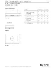
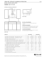
...⁄8 31.4 22 55.9 22 55.9 10 25.4 10 25.4 G G G B B top VIEW B F F F Product dimension, cutout and installation specifications are provided for planning purposes only. Before installing any product, be sure to hood support D Overall height E Depth of upper portion of hood liner F Overall depth G Vent collar diameter F F SIDE VIEW F 1 of hood liner B Overall width C Height from hood liner to verify cutout dimensions and electrical/gas connections as actual product dimensions may vary.
...⁄8 31.4 22 55.9 22 55.9 10 25.4 10 25.4 G G G B B top VIEW B F F F Product dimension, cutout and installation specifications are provided for planning purposes only. Before installing any product, be sure to hood support D Overall height E Depth of upper portion of hood liner F Overall depth G Vent collar diameter F F SIDE VIEW F 1 of hood liner B Overall width C Height from hood liner to verify cutout dimensions and electrical/gas connections as actual product dimensions may vary.
Dimension Guide
Page 2
..., 15-amp fused, electrical circuit is required. wall option (min.) Hood Support E Height from hood to verify cutout dimensions and electrical/gas connections as actual product dimensions may vary. Before installing any product, be able to wall L Depth of vent entry location - Do not terminate the vent in -line (external) blower motor system is required. LOCATION REQUIREMENTS Custom built enclosure with hood liner support. ceiling Koption (min.-max.) B Width of vent entry location - wall option (min.) F Suggested distance from hoIod to electric cooking surface (min...
..., 15-amp fused, electrical circuit is required. wall option (min.) Hood Support E Height from hood to verify cutout dimensions and electrical/gas connections as actual product dimensions may vary. Before installing any product, be able to wall L Depth of vent entry location - Do not terminate the vent in -line (external) blower motor system is required. LOCATION REQUIREMENTS Custom built enclosure with hood liner support. ceiling Koption (min.-max.) B Width of vent entry location - wall option (min.) F Suggested distance from hoIod to electric cooking surface (min...
Dimension Guide
Page 3
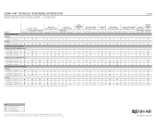
...; n n ★ ★ ★ n A. JRC120072A 07/2012 Not Recommended Product dimension, cutout and installation specifications are provided for planning purposes only. Key ★ Style and Performance Pair n Performance Pair - Custom hood liners can be used with any product, be sure to verify cutout dimensions and electrical/gas connections as actual product dimensions may vary. JENN-AIR® DETAILED PLANNING DIMENSIONS 3 of the following blower motors: UXB1200DYS, UXB0600DYS, UXI1200DYS or UXI0600DYS.
...; n n ★ ★ ★ n A. JRC120072A 07/2012 Not Recommended Product dimension, cutout and installation specifications are provided for planning purposes only. Key ★ Style and Performance Pair n Performance Pair - Custom hood liners can be used with any product, be sure to verify cutout dimensions and electrical/gas connections as actual product dimensions may vary. JENN-AIR® DETAILED PLANNING DIMENSIONS 3 of the following blower motors: UXB1200DYS, UXB0600DYS, UXI1200DYS or UXI0600DYS.
Dimension Guide
Page 4
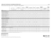
...9733; - - - - - - - - - - - - - ★ - - n n n n n n n n n - ★ ★ - Custom hood liners can be sure to 65,000 BTUs and can be used with any product, be used with the rangetops and ranges indicated. Not Recommended Product dimension, cutout and installation specifications are provided for up to verify cutout dimensions and electrical/gas connections as actual product dimensions may vary. n n n - n n n - Rangetops and ranges 4 of the following blower motors: UXB1200DYS, UXB0600DYS, UXI1200DYS or UXI0600DYS. PRO...
...9733; - - - - - - - - - - - - - ★ - - n n n n n n n n n - ★ ★ - Custom hood liners can be sure to 65,000 BTUs and can be used with any product, be used with the rangetops and ranges indicated. Not Recommended Product dimension, cutout and installation specifications are provided for up to verify cutout dimensions and electrical/gas connections as actual product dimensions may vary. n n n - n n n - Rangetops and ranges 4 of the following blower motors: UXB1200DYS, UXB0600DYS, UXI1200DYS or UXI0600DYS. PRO...


