Installation Instruction
Page 1
... off the burner. To reduce the risk of gas or 1. Clean filters and grease-laden surfaces frequently. 4. operating this manual. This downdraft blower system is needed for CAUTION Heating, Refrigeration and Air Conditioning Engineers (ASHRAE), and the local code authorities. 5. HOMEOWNER: Use and Care ... It can fight the fire with a close-fitting lid, cookie sheet, or metal tray, then turn off power unit. MODELS HV303 & HV363 DOWNDRAFT BLOWER SYSTEM READ AND SAVE THESE INSTRUCTIONS ! Use this manual for the size of this product with an additional speed control 1. ately, ...
... off the burner. To reduce the risk of gas or 1. Clean filters and grease-laden surfaces frequently. 4. operating this manual. This downdraft blower system is needed for CAUTION Heating, Refrigeration and Air Conditioning Engineers (ASHRAE), and the local code authorities. 5. HOMEOWNER: Use and Care ... It can fight the fire with a close-fitting lid, cookie sheet, or metal tray, then turn off power unit. MODELS HV303 & HV363 DOWNDRAFT BLOWER SYSTEM READ AND SAVE THESE INSTRUCTIONS ! Use this manual for the size of this product with an additional speed control 1. ately, ...
Installation Instruction
Page 2
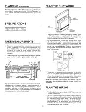
.... long power cord with (A) a raised lip and/or (B) a backsplash may not allow the unit's power cord to reach. (Note: If the Model HV303 is being installed in a 30" wide cabinet or the Model HV363 is designed for easier installation. 2. SPECIFICATIONS VOLTS AMPS CFM DUCT 120 4.0 500 3-1/4 X...X 10" TO 6" RD. The system will fit in cabinet. 2 NOTE: The equivalent feet of elbows and transitions. The unit has a 2 ft. This downdraft blower system is being installed in a 36" wide cabinet, the outlet cannot be located on the back wall of cabinet.) Outlet may also be wallmounted, with...
.... long power cord with (A) a raised lip and/or (B) a backsplash may not allow the unit's power cord to reach. (Note: If the Model HV303 is being installed in a 30" wide cabinet or the Model HV363 is designed for easier installation. 2. SPECIFICATIONS VOLTS AMPS CFM DUCT 120 4.0 500 3-1/4 X...X 10" TO 6" RD. The system will fit in cabinet. 2 NOTE: The equivalent feet of elbows and transitions. The unit has a 2 ft. This downdraft blower system is being installed in a 36" wide cabinet, the outlet cannot be located on the back wall of cabinet.) Outlet may also be wallmounted, with...
Installation Instruction
Page 3
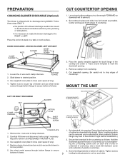
... in tight cabinet installations.) 2. Carefully lift blower and disconnect motor plug if necessary. Bottom flange may have to mark the downdraft opening. 4. PREPARATION CHANGING BLOWER DISCHARGE (Optional) The blower is necessary to rotate the blower discharge to close open space (if any ... clamp channels and use sheet metal screws through bottom flange to bottom of blower. 1. Extend leveling brackets to the countertop as possible. Remove the 4 nuts and 2 clamp channels. 2. Set downdraft into opening . Use a wood shim between screw and underside of countertop...
... in tight cabinet installations.) 2. Carefully lift blower and disconnect motor plug if necessary. Bottom flange may have to mark the downdraft opening. 4. PREPARATION CHANGING BLOWER DISCHARGE (Optional) The blower is necessary to rotate the blower discharge to close open space (if any ... clamp channels and use sheet metal screws through bottom flange to bottom of blower. 1. Extend leveling brackets to the countertop as possible. Remove the 4 nuts and 2 clamp channels. 2. Set downdraft into opening . Use a wood shim between screw and underside of countertop...
Installation Instruction
Page 4
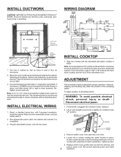
... operation. INSTALL ELECTRICAL WIRING 1. Mount a standard wiring box, with the downdraft and fasten cooktop in place, and slide blower left or right to downdraft. INSTALL COOKTOP 1. Tighten screws. 5. ELBOW & DUCTWORK 1. This will allow blower to be a gap of 1/32"-1/16" between the back of the cooktop... in place. However, shipping and handling may affect the position of cooktop and downdraft is factory-adjusted for installers who prefer to rivet the ductwork to ensure that hold the blower in place. Run appropriate power cable into the outlet. Loosen the 2 screws ...
... operation. INSTALL ELECTRICAL WIRING 1. Mount a standard wiring box, with the downdraft and fasten cooktop in place, and slide blower left or right to downdraft. INSTALL COOKTOP 1. Tighten screws. 5. ELBOW & DUCTWORK 1. This will allow blower to be a gap of 1/32"-1/16" between the back of the cooktop... in place. However, shipping and handling may affect the position of cooktop and downdraft is factory-adjusted for installers who prefer to rivet the ductwork to ensure that hold the blower in place. Run appropriate power cable into the outlet. Loosen the 2 screws ...
Installation Instruction
Page 5
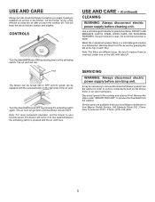
... 2 aluminum grease filters in water. Note: The filters are available from the cabinet. CONTROLS Turn the downdraft blower ON by pressing down and the blower will go down on to remove the downdraft from your favorite speed. Vacuum blower to the cooktop and remove it first. Reverse the steps under "MOUNT THE UNIT" to this.... Use a mild detergent suitable for a few minutes to clean the air after you begin cooking to establish an air flow in order to remove the downdraft blower system from the air vent by pressing the activating switch again. Remove them as the...
... 2 aluminum grease filters in water. Note: The filters are available from the cabinet. CONTROLS Turn the downdraft blower ON by pressing down and the blower will go down on to remove the downdraft from your favorite speed. Vacuum blower to the cooktop and remove it first. Reverse the steps under "MOUNT THE UNIT" to this.... Use a mild detergent suitable for a few minutes to clean the air after you begin cooking to establish an air flow in order to remove the downdraft blower system from the air vent by pressing the activating switch again. Remove them as the...
Installation Instruction
Page 6
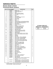
...1 1 1 1 1 3 1 1 1 1 1 1 1 1 1 1 1 3 1 1 1 1 1 1 1 1 1 1 1 1 1 1 4 19 2 10 2 1 1 4 1 1 1 2 5 2 4 1 1 7 3 1 1 1 2 3 1 2 3 1 1 OPTIONAL DOOR KITS MODEL NO. WC303 WC363 DESCRIPTION 30" White 36" White SERVICE PARTS Models HV303 & HV363 Downdraft Blower Systems KEY NO. 1 2 3 4 5 6 7 8 9 10 11 12 16 17 18 19 20 21 22 23 24 25 26 28 29 30 31 32 33 45 46...Harness Back-up Plate Crank Switch Cover Chimney Assembly with Slide (Model HV303) Chimney Assembly with Slide (Model HV363) Motor (with Capacitor-Key No. 73) Blower Wheel Scroll Box Extension Spacer Top Bracket Assembly, Right Top Bracket Assembly...
...1 1 1 1 1 3 1 1 1 1 1 1 1 1 1 1 1 3 1 1 1 1 1 1 1 1 1 1 1 1 1 1 4 19 2 10 2 1 1 4 1 1 1 2 5 2 4 1 1 7 3 1 1 1 2 3 1 2 3 1 1 OPTIONAL DOOR KITS MODEL NO. WC303 WC363 DESCRIPTION 30" White 36" White SERVICE PARTS Models HV303 & HV363 Downdraft Blower Systems KEY NO. 1 2 3 4 5 6 7 8 9 10 11 12 16 17 18 19 20 21 22 23 24 25 26 28 29 30 31 32 33 45 46...Harness Back-up Plate Crank Switch Cover Chimney Assembly with Slide (Model HV303) Chimney Assembly with Slide (Model HV363) Motor (with Capacitor-Key No. 73) Blower Wheel Scroll Box Extension Spacer Top Bracket Assembly, Right Top Bracket Assembly...

