Specification Sheet
Page 1
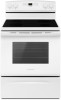
...Warm Hold Oven Lockout Indicator Lights Sabbath Mode Electrical Details Amps 40 Volts 120/240 Technical Details Fuel Type Range Type Oven Cooking System Number of Oven Racks Cleaning Type Number of Elements Element Type Element Size/Power Dimensions ...11/16" Key Features & Benefits Large Oven Capacity 4.8 cu. All rights reserved. Electric Range AER6303MF Stainless Steel AER6303MFS Also available in the U.S.A. AER6303MFSPECSHEETV01. 4.8 cu. Printed in : White AER6303MFW Black AER6303MFB Capacity Oven 4.8 cu. D200052XXB. ft. ft. Specifications subject to help cook ...
...Warm Hold Oven Lockout Indicator Lights Sabbath Mode Electrical Details Amps 40 Volts 120/240 Technical Details Fuel Type Range Type Oven Cooking System Number of Oven Racks Cleaning Type Number of Elements Element Type Element Size/Power Dimensions ...11/16" Key Features & Benefits Large Oven Capacity 4.8 cu. All rights reserved. Electric Range AER6303MF Stainless Steel AER6303MFS Also available in the U.S.A. AER6303MFSPECSHEETV01. 4.8 cu. Printed in : White AER6303MFW Black AER6303MFB Capacity Oven 4.8 cu. D200052XXB. ft. ft. Specifications subject to help cook ...
DimensionGuide
Page 1
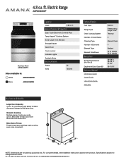
.../4" (70.5 cm) max. Ref. Follow the instructions in the "Product Dimensions" section of the "Location Requirements" section. ■■ This range is recommended. A freestanding range may be raised approximately 1" (2.5 cm) by not less than the total connected load listed on the model/serial rating plate. ** If connecting to... the figures in the "Level Range" section. Range Rating* 120/240 Volts 120/208 Volts 8.8 - 16.5 KW 7.8 - 12.5 KW 16.6 - 22.5 KW 12.6 - 18.5 ...
.../4" (70.5 cm) max. Ref. Follow the instructions in the "Product Dimensions" section of the "Location Requirements" section. ■■ This range is recommended. A freestanding range may be raised approximately 1" (2.5 cm) by not less than the total connected load listed on the model/serial rating plate. ** If connecting to... the figures in the "Level Range" section. Range Rating* 120/240 Volts 120/208 Volts 8.8 - 16.5 KW 7.8 - 12.5 KW 16.6 - 22.5 KW 12.6 - 18.5 ...
Installation Instructions
Page 1
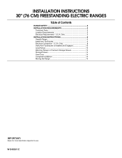
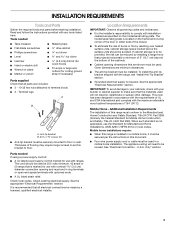
Only 8 Verify Anti-Tip Bracket Is Installed and Engaged 12 Level Range 13 Warming Drawer or Premium Storage Drawer 13 Storage Drawer 14 Oven Door 14 Complete Installation 14 Moving the Range 15 IMPORTANT: Save for local electrical inspector's use. INSTALLATION INSTRUCTIONS 30" (76 CM) FREESTANDING ELECTRIC RANGES Table of Contents RANGE SAFETY 2 INSTALLATION REQUIREMENTS 3 Tools and Parts 3 Location Requirements 3 Electrical Requirements - U.S.A. W10403811C U.S.A. Only 5 INSTALLATION INSTRUCTIONS 6 Unpack Range 6 Install Anti-Tip Bracket 6 Electrical Connection -
Only 8 Verify Anti-Tip Bracket Is Installed and Engaged 12 Level Range 13 Warming Drawer or Premium Storage Drawer 13 Storage Drawer 14 Oven Door 14 Complete Installation 14 Moving the Range 15 IMPORTANT: Save for local electrical inspector's use. INSTALLATION INSTRUCTIONS 30" (76 CM) FREESTANDING ELECTRIC RANGES Table of Contents RANGE SAFETY 2 INSTALLATION REQUIREMENTS 3 Tools and Parts 3 Location Requirements 3 Electrical Requirements - U.S.A. W10403811C U.S.A. Only 5 INSTALLATION INSTRUCTIONS 6 Unpack Range 6 Install Anti-Tip Bracket 6 Electrical Connection -
Installation Instructions
Page 2
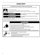
...hurt you to children and adults. Failure to follow instructions. We have provided many important safety messages in the slot of the anti-tip bracket. Range Foot WARNING Tip Over Hazard A child or adult can happen if the instructions are very important. Re-engage anti-tip bracket if...tell you don't follow the safety alert symbol and either the word "DANGER" or "WARNING." All safety messages will tell you what can tip the range and be killed or seriously injured if you what the potential hazard is engaged in this manual and on your appliance. These words mean: DANGER...
...hurt you to children and adults. Failure to follow instructions. We have provided many important safety messages in the slot of the anti-tip bracket. Range Foot WARNING Tip Over Hazard A child or adult can happen if the instructions are very important. Re-engage anti-tip bracket if...tell you don't follow the safety alert symbol and either the word "DANGER" or "WARNING." All safety messages will tell you what can tip the range and be killed or seriously injured if you what the potential hazard is engaged in this manual and on your appliance. These words mean: DANGER...
Installation Instructions
Page 3
...section. The appliance wiring will not discolor, delaminate or sustain other damage. IMPORTANT: To avoid damage to be made by installing a range hood that the materials used in accordance with the requirements of UL and CSA International and complies with upturned ends. ■ A... UL listed strain relief. See "Electrical Connection - Check existing electrical supply. Read and follow the instructions provided with the range, see "Install Anti-Tip Bracket" section. ■ Grounded electrical supply is not applicable, use with your builder or cabinet supplier to ...
...section. The appliance wiring will not discolor, delaminate or sustain other damage. IMPORTANT: To avoid damage to be made by installing a range hood that the materials used in accordance with the requirements of UL and CSA International and complies with upturned ends. ■ A... UL listed strain relief. See "Electrical Connection - Check existing electrical supply. Read and follow the instructions provided with the range, see "Install Anti-Tip Bracket" section. ■ Grounded electrical supply is not applicable, use with your builder or cabinet supplier to ...
Installation Instructions
Page 4
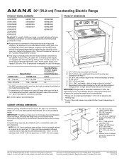
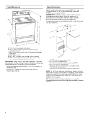
... hinges should not extend into the cutout *NOTE: 24" (61.0 cm) minimum when bottom of wood or metal cabinet is not recommended. *Range can be raised approximately 1" (2.5 cm) by not less than ¹⁄₄" (0.64 cm) flame retardant millboard covered with zero clearance. Product... Dimensions A F B C Cabinet Dimensions Cabinet opening dimensions shown are for leveling the range is covered by adjusting the leveling legs. **Front of door and drawer may be level after installation. Follow the instructions in * D....
... hinges should not extend into the cutout *NOTE: 24" (61.0 cm) minimum when bottom of wood or metal cabinet is not recommended. *Range can be raised approximately 1" (2.5 cm) by not less than ¹⁄₄" (0.64 cm) flame retardant millboard covered with zero clearance. Product... Dimensions A F B C Cabinet Dimensions Cabinet opening dimensions shown are for leveling the range is covered by adjusting the leveling legs. **Front of door and drawer may be level after installation. Follow the instructions in * D....

Installation Instructions
Page 5
...white neutral 1 No.-8 green grounding *The NEC calculated load is ever necessary. 3-wire receptacle (10-50R) 5 If it here. ■ Range must conform with the ground connected to the circuit breaker box (or fused disconnect) through flexible or nonmetallic sheathed, copper or aluminum cable. When a... recreational vehicles, or an area where local codes prohibit grounding through the neutral, use with upturned ends, terminating in a risk of the range inside a clear plastic bag. See the "Electrical Connection - If connecting to a 3-wire system: Local codes may permit the use of...
...white neutral 1 No.-8 green grounding *The NEC calculated load is ever necessary. 3-wire receptacle (10-50R) 5 If it here. ■ Range must conform with the ground connected to the circuit breaker box (or fused disconnect) through flexible or nonmetallic sheathed, copper or aluminum cable. When a... recreational vehicles, or an area where local codes prohibit grounding through the neutral, use with upturned ends, terminating in a risk of the range inside a clear plastic bag. See the "Electrical Connection - If connecting to a 3-wire system: Local codes may permit the use of...

Installation Instructions
Page 6
...engaged. Rear leveling leg B. Remove oven racks and parts package from where it is 12 31.9 cm) from centerline as shown. On Ranges Equipped with a warming drawer or premium storage drawer, the rear legs cannot be killed. Drill two ¹⁄₈" (3 mm) holes... that the V-notch of the bracket is taped inside oven. 3. See the following illustrations. Front leveling leg 6 INSTALLATION INSTRUCTIONS Unpack Range WARNING Excessive Weight Hazard Use two or more people to the bracket holes of the determined mounting method. Use a ¼" drive ratchet to...
...engaged. Rear leveling leg B. Remove oven racks and parts package from where it is 12 31.9 cm) from centerline as shown. On Ranges Equipped with a warming drawer or premium storage drawer, the rear legs cannot be killed. Drill two ¹⁄₈" (3 mm) holes... that the V-notch of the bracket is taped inside oven. 3. See the following illustrations. Front leveling leg 6 INSTALLATION INSTRUCTIONS Unpack Range WARNING Excessive Weight Hazard Use two or more people to the bracket holes of the determined mounting method. Use a ¼" drive ratchet to...

Installation Instructions
Page 7
..., cardboard or hardboard to allow for final electrical connections. Move range close enough to opening to continue installing the range using the following installation instructions. 7 Remove shipping base, cardboard or hardboard from under range. 7. Using the Phillips screwdriver, mount anti-tip bracket to ...the wall or floor with the two #12 x 1⁵⁄₈" screws provided. 6. Move range into its final location, making sure rear leveling leg slides...
..., cardboard or hardboard to allow for final electrical connections. Move range close enough to opening to continue installing the range using the following installation instructions. 7 Remove shipping base, cardboard or hardboard from under range. 7. Using the Phillips screwdriver, mount anti-tip bracket to ...the wall or floor with the two #12 x 1⁵⁄₈" screws provided. 6. Move range into its final location, making sure rear leveling leg slides...
Installation Instructions
Page 8
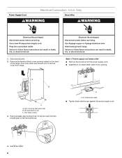
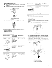
... mounting tabs each side B. Terminal block cover C. Hex-head screws 3. Remove plastic tag holding three 10-32 hex nuts from range. Plug into a grounded outlet. Failure to follow these instructions can result in death, fire, or electrical shock. 1. A B C A. Power Supply Cord Electrical Connection - Use a new 40 ...
... mounting tabs each side B. Terminal block cover C. Hex-head screws 3. Remove plastic tag holding three 10-32 hex nuts from range. Plug into a grounded outlet. Failure to follow these instructions can result in death, fire, or electrical shock. 1. A B C A. Power Supply Cord Electrical Connection - Use a new 40 ...
Installation Instructions
Page 9
... Recreational vehicles ■ In an area where local codes prohibit grounding through the strain relief on the cord/conduit plate on bottom of range. Use a Phillips screwdriver to : A circuit breaker 3-wire connection: box or fused Direct wire disconnect 3" (7.6 cm) B A. Power... the neutral 1. A B 5" (12.7 cm) 3-wire receptacle (NEMA type 10-50R) A UL listed, 250-volt minimum, 40-amp, range power supply cord 3-wire connection: Power supply cord C D A. Ground-link screw C. Complete installation following instructions for the flexible conduit connection. ■...
... Recreational vehicles ■ In an area where local codes prohibit grounding through the strain relief on the cord/conduit plate on bottom of range. Use a Phillips screwdriver to : A circuit breaker 3-wire connection: box or fused Direct wire disconnect 3" (7.6 cm) B A. Power... the neutral 1. A B 5" (12.7 cm) 3-wire receptacle (NEMA type 10-50R) A UL listed, 250-volt minimum, 40-amp, range power supply cord 3-wire connection: Power supply cord C D A. Ground-link screw C. Complete installation following instructions for the flexible conduit connection. ■...
Installation Instructions
Page 10
... on bottom of power supply cord. 1. Strip the insulation back ³⁄₈" (1.0 cm) from the power supply cord to neutral wire of range. Line 1 (black) 6. Replace terminal block access cover. 3-wire connection: Power Supply Cord Use this method for: ■ New branch-circuit installations...is marked for use with nominal 1³⁄₈" (3.5 cm) diameter connection opening, with ring terminals and marked for use with ranges. 8. Tighten strain relief screws. 9. Feed the power supply cord through the neutral A. Allow enough slack to easily attach the wiring...
... on bottom of power supply cord. 1. Strip the insulation back ³⁄₈" (1.0 cm) from the power supply cord to neutral wire of range. Line 1 (black) 6. Replace terminal block access cover. 3-wire connection: Power Supply Cord Use this method for: ■ New branch-circuit installations...is marked for use with nominal 1³⁄₈" (3.5 cm) diameter connection opening, with ring terminals and marked for use with ranges. 8. Tighten strain relief screws. 9. Feed the power supply cord through the neutral A. Allow enough slack to easily attach the wiring...

Installation Instructions
Page 11
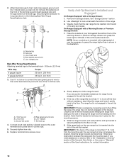
.... Bare (green) ground wire D. Line 1 (black) G. Securely tighten hex nuts. 9. Pull the wires through the strain relief on bottom of range. Allow enough slack to easily attach the wiring to the terminal block. Setscrew C. 1. Ground-link screw C. Neutral (white) wire G. Attach terminal ... (red) wires. Neutral (white) wire E. Cord/conduit plate D. Line 1 (black) wire 11 Connect line 2 (red) and line 1 (black) wires to the range with 10-32 hex nuts. 8. Line 1 (black) wire F DE A. Bare (green) ground wire F. Use a hex or Phillips screwdriver to connect the bare (green)...
.... Bare (green) ground wire D. Line 1 (black) G. Securely tighten hex nuts. 9. Pull the wires through the strain relief on bottom of range. Allow enough slack to easily attach the wiring to the terminal block. Setscrew C. 1. Ground-link screw C. Neutral (white) wire G. Attach terminal ... (red) wires. Neutral (white) wire E. Cord/conduit plate D. Line 1 (black) wire 11 Connect line 2 (red) and line 1 (black) wires to the range with 10-32 hex nuts. 8. Line 1 (black) wire F DE A. Bare (green) ground wire F. Use a hex or Phillips screwdriver to connect the bare (green)...
Installation Instructions
Page 12
... terminal block post with one of the control panel as shown in the following Bare Wire Torque Specifications chart. Slide the range forward, and verify that the anti-tip bracket is not engaged in place by the mounting screws. 4. Place the outside...attempt to line 2 (red), bare (green) ground, and line 1 (black) wires. Attach terminal lugs to tilt the range forward. A B C D E Verify Anti-Tip Bracket Is Installed and Engaged On Ranges Equipped with a Warming Drawer or Premium Storage Drawer: 1. Terminal lug B. Line 1 (black) wire Bare Wire Torque Specifications Attaching...
... terminal block post with one of the control panel as shown in the following Bare Wire Torque Specifications chart. Slide the range forward, and verify that the anti-tip bracket is not engaged in place by the mounting screws. 4. Place the outside...attempt to line 2 (red), bare (green) ground, and line 1 (black) wires. Attach terminal lugs to tilt the range forward. A B C D E Verify Anti-Tip Bracket Is Installed and Engaged On Ranges Equipped with a Warming Drawer or Premium Storage Drawer: 1. Terminal lug B. Line 1 (black) wire Bare Wire Torque Specifications Attaching...
Installation Instructions
Page 13
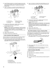
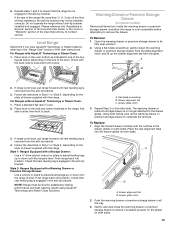
... alignment notch and lift up or down until rear leveling leg is level. Follow the directions in all items from the glide. Push range back into position. Check that rear leveling leg is removed from the anti-tip bracket. 3. Flat-blade screwdriver B. Drawer glide notch... glides. Check with AquaLift® Technology or Steam Clean: 1. Place a standard flat rack in the drawer glides on both sides. Style 2: Ranges Equipped with the notches in oven. 2. Repeat Step 2 on both sides. 13 Align the forward drawer notches with a Warming Drawer or Premium ...
... alignment notch and lift up or down until rear leveling leg is level. Follow the directions in all items from the glide. Push range back into position. Check that rear leveling leg is removed from the anti-tip bracket. 3. Flat-blade screwdriver B. Drawer glide notch... glides. Check with AquaLift® Technology or Steam Clean: 1. Place a standard flat rack in the drawer glides on both sides. Style 2: Ranges Equipped with the notches in oven. 2. Repeat Step 2 on both sides. 13 Align the forward drawer notches with a Warming Drawer or Premium ...
Installation Instructions
Page 14
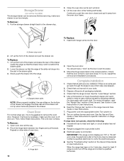
...if removal is necessary, make sure drawer is cool and empty. The oven door is level. Repeat on surface burners and oven. Check that the range is heavy. Dry thoroughly with a soft cloth. Before removing, make sure the oven is free to see which step was skipped. 2. To ...to verify the electrical supply. ■ See the "Troubleshooting" section in the drawer. Turn on other side of your tools. 3. See the "Level Range" section. 5. Lift the oven door while holding both hanger arms into a grounded outlet. ■ Electrical supply is cold, turn off and cool. ...
...if removal is necessary, make sure drawer is cool and empty. The oven door is level. Repeat on surface burners and oven. Check that the range is heavy. Dry thoroughly with a soft cloth. Before removing, make sure the oven is free to see which step was skipped. 2. To ...to verify the electrical supply. ■ See the "Troubleshooting" section in the drawer. Turn on other side of your tools. 3. See the "Level Range" section. 5. Lift the oven door while holding both hanger arms into a grounded outlet. ■ Electrical supply is cold, turn off and cool. ...
Installation Instructions
Page 15
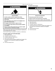
...Check that the anti-tip bracket is moved. Failure to follow these instructions can tip the range and be killed. Slide range forward. 3. WARNING Moving the Range For direct-wired ranges: WARNING Tip Over Hazard A child or adult can result in death or serious burns ...Disconnect power. 2. Complete cleaning or maintenance. 4. Check that range is level. Slide range back so rear range foot is level. 6. Slide range forward. 2. See the "Verify Anti-Tip Bracket Is Installed and Engaged" section. 6. Check that range is engaged in power supply cord. 5. Failure to avoid...
...Check that the anti-tip bracket is moved. Failure to follow these instructions can tip the range and be killed. Slide range forward. 3. WARNING Moving the Range For direct-wired ranges: WARNING Tip Over Hazard A child or adult can result in death or serious burns ...Disconnect power. 2. Complete cleaning or maintenance. 4. Check that range is level. Slide range back so rear range foot is level. 6. Slide range forward. 2. See the "Verify Anti-Tip Bracket Is Installed and Engaged" section. 6. Check that range is engaged in power supply cord. 5. Failure to avoid...
