Owners Manual
Page 5
Contents Introduction ...2 WARNING ...4 CAUTION ...5 PRECAUTIONS ...5 Installation ...6 Mounting the End Covers ...7 Connections ...8 Cautions on wire lead connections ...10 Mounting the Terminal Cover ...12 Switch Settings 14 Examples of System Expansion 15 Information ...18 In case of difficulty ...18 Specifications ...19 Service Care ...20 1-EN
Contents Introduction ...2 WARNING ...4 CAUTION ...5 PRECAUTIONS ...5 Installation ...6 Mounting the End Covers ...7 Connections ...8 Cautions on wire lead connections ...10 Mounting the Terminal Cover ...12 Switch Settings 14 Examples of System Expansion 15 Information ...18 In case of difficulty ...18 Specifications ...19 Service Care ...20 1-EN

Owners Manual
Page 6
... in reproduction speed and time measurement, to deliver the best possible sound in this new era with an approach called "micro-dynamics." Alpine constantly strives to maximize the musical sensory experience. The best sound in the mobile environment promises the most advanced multimedia experience.... To overcome these severe listening conditions, Alpine has developed its unique technology and expertise accumulated through years of experience. This approach consists of home audio. For an exciting and wide range of emotional experience, sound is more important than ever, and is...
... in reproduction speed and time measurement, to deliver the best possible sound in this new era with an approach called "micro-dynamics." Alpine constantly strives to maximize the musical sensory experience. The best sound in the mobile environment promises the most advanced multimedia experience.... To overcome these severe listening conditions, Alpine has developed its unique technology and expertise accumulated through years of experience. This approach consists of home audio. For an exciting and wide range of emotional experience, sound is more important than ever, and is...
Owners Manual
Page 7
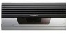
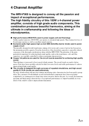
... ideas of glass epoxy. 4 Channel Amplifier The MRV-F900 is designed to achieve unprecedented high sound quality. Even the electrolyte of the electrolytic capacitor is specially ordered, a measure of the sound to achieve maximum time precision. I Exclusive audio high speed, high current SBD (Schottky barrier diode) used for the circuit boards essential for their low noise levels and stable performance to convey all the...
... ideas of glass epoxy. 4 Channel Amplifier The MRV-F900 is designed to achieve unprecedented high sound quality. Even the electrolyte of the electrolytic capacitor is specially ordered, a measure of the sound to achieve maximum time precision. I Exclusive audio high speed, high current SBD (Schottky barrier diode) used for the circuit boards essential for their low noise levels and stable performance to convey all the...
Owners Manual
Page 8
... location before performing these functions. can result in an accident. Never cut away cable insulation to supply power to electrical shorts. Failure to contact, damage or obstruct pipes, fuel lines, tanks or electrical wiring. DO NOT USE BOLTS OR NUTS IN THE BRAKE OR STEERING SYSTEMS TO MAKE GROUND CONNECTIONS. Using such parts could disable control of the wire and result in serious injury...
... location before performing these functions. can result in an accident. Never cut away cable insulation to supply power to electrical shorts. Failure to contact, damage or obstruct pipes, fuel lines, tanks or electrical wiring. DO NOT USE BOLTS OR NUTS IN THE BRAKE OR STEERING SYSTEMS TO MAKE GROUND CONNECTIONS. Using such parts could disable control of the wire and result in serious injury...
Owners Manual
Page 9
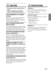
... DUST. Installation Location Make sure the MRV-F900 will prevent crimping and damage to : • Direct sun and heat • High humidity and water • Excessive dust • Excessive vibrations Maintenance If you purchased this unit requires special technical skill and experience. HALT USE IMMEDIATELY IF A PROBLEM APPEARS. Failure to your authorized Alpine dealer or the nearest Alpine Service Center for servicing. 5-EN...
... DUST. Installation Location Make sure the MRV-F900 will prevent crimping and damage to : • Direct sun and heat • High humidity and water • Excessive dust • Excessive vibrations Maintenance If you purchased this unit requires special technical skill and experience. HALT USE IMMEDIATELY IF A PROBLEM APPEARS. Failure to your authorized Alpine dealer or the nearest Alpine Service Center for servicing. 5-EN...
Owners Manual
Page 10
... high power output of the MRV-F900, considerable heat is produced when the amplifier is a good ground by checking continuity to the same ground point. For alternate installation locations, please contact your authorized Alpine dealer. 1. Be sure this reason, the amplifier should be mounted in operation. Drill the screw holes. 4. Position the MRV-F900 over the screw holes, and secure with four self-tapping screws. Using the amplifier...
... high power output of the MRV-F900, considerable heat is produced when the amplifier is a good ground by checking continuity to the same ground point. For alternate installation locations, please contact your authorized Alpine dealer. 1. Be sure this reason, the amplifier should be mounted in operation. Drill the screw holes. 4. Position the MRV-F900 over the screw holes, and secure with four self-tapping screws. Using the amplifier...

Owners Manual
Page 11
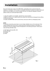
... bottom upwards, in the opposite direction of double face tape 7 to the brackets 5. Mounting the End Covers • The product's appearance can be improved by mounting the end covers on the main unit after installation. • Mount the end covers after installing the main unit. 1 Mounting the brackets 1) Use the included machine screws 6 to mount the three... once it is mounted. 1) Peel off the paper from one side of the included double face tape 7. 2) Apply one piece of when the bracket was installed. 8 Fig. 4 9 5 Fig. 5 7-EN Set the bracket 5 vertically from the top side.
... bottom upwards, in the opposite direction of double face tape 7 to the brackets 5. Mounting the End Covers • The product's appearance can be improved by mounting the end covers on the main unit after installation. • Mount the end covers after installing the main unit. 1 Mounting the brackets 1) Use the included machine screws 6 to mount the three... once it is mounted. 1) Peel off the paper from one side of the included double face tape 7. 2) Apply one piece of when the bracket was installed. 8 Fig. 4 9 5 Fig. 5 7-EN Set the bracket 5 vertically from the top side.
Owners Manual
Page 12
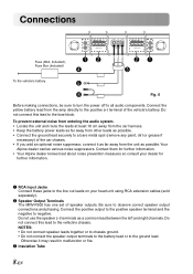
...-3 SPEAKER OUTPUT INPUT CH-4 21 3 To the vehicle's battery 5 6 Fig. 6 Before making connections, be sure to turn the power off to the line out leads on your dealer for further information. 1 RCA Input Jacks Connect these jacks to all audio components. Contact them for further information. • Your Alpine dealer knows best about noise prevention measures so consult your head unit using RCA extension cables (sold separately). 2 Speaker Output Terminals The MRV-F900 has one set...
...-3 SPEAKER OUTPUT INPUT CH-4 21 3 To the vehicle's battery 5 6 Fig. 6 Before making connections, be sure to turn the power off to the line out leads on your dealer for further information. 1 RCA Input Jacks Connect these jacks to all audio components. Contact them for further information. • Your Alpine dealer knows best about noise prevention measures so consult your head unit using RCA extension cables (sold separately). 2 Speaker Output Terminals The MRV-F900 has one set...
Owners Manual
Page 13
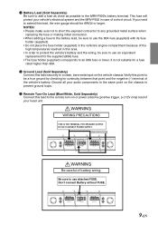
... connector to any grounded metal surface when replacing the fuse or making initial connection. • When adding a fuse to the battery lead, be sure to an 80A fuse or lower. SPEAKER OUTPUT BATTERY GND RENOTE POWER SUPPLY + BRIDGED - + CH-3 - + CH-4 - Verify this lead, the wire gauge should be AWG4 or larger. This fuse will protect your head unit. If you need to extend this point to be sure to the MRV-F900's battery terminal. CONNECT POWER...
... connector to any grounded metal surface when replacing the fuse or making initial connection. • When adding a fuse to the battery lead, be sure to an 80A fuse or lower. SPEAKER OUTPUT BATTERY GND RENOTE POWER SUPPLY + BRIDGED - + CH-3 - + CH-4 - Verify this lead, the wire gauge should be AWG4 or larger. This fuse will protect your head unit. If you need to extend this point to be sure to the MRV-F900's battery terminal. CONNECT POWER...

Owners Manual
Page 14
...; Wire Size (Battery Lead, Ground Lead): Recommended wire size for this unit is AWG4 or larger. • Wire Size (Remote Turn-on wire lead connections • Use Power Supply wire sold at your dealer's store. • Refer to make this unit is too long, an electrical short-circuit may occur causing operation failure or sound interruption. • On the other hand, if the length is AWG8 - AWG14. • If the wire...
...; Wire Size (Battery Lead, Ground Lead): Recommended wire size for this unit is AWG4 or larger. • Wire Size (Remote Turn-on wire lead connections • Use Power Supply wire sold at your dealer's store. • Refer to make this unit is too long, an electrical short-circuit may occur causing operation failure or sound interruption. • On the other hand, if the length is AWG8 - AWG14. • If the wire...

Owners Manual
Page 15
Turn the cap 1 counterclockwise. 2) Turn the hexagon screw 3 of the fuse terminal 2 with the Hexagonal Wrench (Included), to fix the lead. (Fig. 9) Before making this connection, use the cabling to cover any exposed wire extending beyond the terminal. 3 Slide the battery lead into the fuse block. • Slide the battery lead (sold separately) through the cap 1 . 5) Insert the tip of the battery lead 5 into the lead terminal. Insert...
Turn the cap 1 counterclockwise. 2) Turn the hexagon screw 3 of the fuse terminal 2 with the Hexagonal Wrench (Included), to fix the lead. (Fig. 9) Before making this connection, use the cabling to cover any exposed wire extending beyond the terminal. 3 Slide the battery lead into the fuse block. • Slide the battery lead (sold separately) through the cap 1 . 5) Insert the tip of the battery lead 5 into the lead terminal. Insert...

Owners Manual
Page 16
... the vehicle may damage the wires or cause short-circuiting. e p w 12-EN Fig. 11 q p Fig. 10 2 Mounting the terminal cover 1) Before mounting the terminal cover • Fasten the wires securely together in a position in which they will not touch the terminal cover. 2) Use the two included hexagon screws (M3) e to mount the included terminal cover w to remove the two...
... the vehicle may damage the wires or cause short-circuiting. e p w 12-EN Fig. 11 q p Fig. 10 2 Mounting the terminal cover 1) Before mounting the terminal cover • Fasten the wires securely together in a position in which they will not touch the terminal cover. 2) Use the two included hexagon screws (M3) e to mount the included terminal cover w to remove the two...

Owners Manual
Page 17
q w Fig. 12 p 13-EN NOTES: • Be sure to fasten the door. Failure to do not come loose due to vibrations while the vehicle is used with the door open. 3 Fastening the door 1) Close the door p. 2) Mount the door p using the two original hexagonal screws q. * Tighten the screws securely so that they do so may lead to malfunction. • The warranty will be invalidated if the unit is moving.
q w Fig. 12 p 13-EN NOTES: • Be sure to fasten the door. Failure to do not come loose due to vibrations while the vehicle is used with the door open. 3 Fastening the door 1) Close the door p. 2) Mount the door p using the two original hexagonal screws q. * Tighten the screws securely so that they do so may lead to malfunction. • The warranty will be invalidated if the unit is moving.
Owners Manual
Page 18
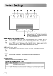
...-EN When you finish 13 the switch setting, close the door and fix with the indicator. • Protection indicator (PROTECTION) Blue Red Condition Light Amplifier circuit is abnormal. Using a dynamic CD as a NOM(1.0V) source, increase the head unit volume until the sound from the speakers becomes distorted. Then, reduce the vol- MODE 13 Status indicator Amplifier status can be confirmed with the original hexagon screws. 7 , 8 , 11 , 12 Input Gain Adjustment Control Set the MRV-F900 input gain to the "BRIDGED" position.
...-EN When you finish 13 the switch setting, close the door and fix with the indicator. • Protection indicator (PROTECTION) Blue Red Condition Light Amplifier circuit is abnormal. Using a dynamic CD as a NOM(1.0V) source, increase the head unit volume until the sound from the speakers becomes distorted. Then, reduce the vol- MODE 13 Status indicator Amplifier status can be confirmed with the original hexagon screws. 7 , 8 , 11 , 12 Input Gain Adjustment Control Set the MRV-F900 input gain to the "BRIDGED" position.

Owners Manual
Page 19
... BRIDGED MODE NORMAL BRIDGED MODE CH-1 INPUT CH-2 + BRIDGED - + CH-1 - + CH-2 - CH-3 SPEAKER OUTPUT INPUT CH-4 (L) (R) (L) (R) 14 14 (L) (R) (L) (R) Head Unit * NOTES: • Please make sure not to short the exposed connector to any grounded metal surface when replacing the fuse or making initial connection. • When adding a fuse to the battery lead, be sure to use an equivalent replacement for a fuse rated higher than 80A. Remote Turn-On Lead 14 RCA Extension Cable (Sold Separately) 15 Fuse (80A, Included), Fuse...
... BRIDGED MODE NORMAL BRIDGED MODE CH-1 INPUT CH-2 + BRIDGED - + CH-1 - + CH-2 - CH-3 SPEAKER OUTPUT INPUT CH-4 (L) (R) (L) (R) 14 14 (L) (R) (L) (R) Head Unit * NOTES: • Please make sure not to short the exposed connector to any grounded metal surface when replacing the fuse or making initial connection. • When adding a fuse to the battery lead, be sure to use an equivalent replacement for a fuse rated higher than 80A. Remote Turn-On Lead 14 RCA Extension Cable (Sold Separately) 15 Fuse (80A, Included), Fuse...
Owners Manual
Page 20
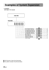
Examples of System Expansion • SYSTEM B (4ch input, 11ch output) CDA-7990 PXA-H900 FUSE 15A POWER SUPPLY BATTERY GND CENTER SUBWOOFER REAR FRONT LOW FRONT MID FRONT HIGH (L) GUIDE INPUT OUTPUT (R) Front Tweeter Output (L) 14 Front Tweeter Output (R) Front Mid Range Output (L) 14 Front Mid Range Output (R) Front Mid Bass Output (L) 14 Front Mid Bass Output (R) Rear Output (L) 14 Rear Output (R) Subwoofer Output (L) 14 Subwoofer Output (R) Center Output abcdefghijk 14 14 RCA Extension Cable (Sold Separately) 15 Fuse (80A, Included), Fuse Box (Included) 16-EN
Examples of System Expansion • SYSTEM B (4ch input, 11ch output) CDA-7990 PXA-H900 FUSE 15A POWER SUPPLY BATTERY GND CENTER SUBWOOFER REAR FRONT LOW FRONT MID FRONT HIGH (L) GUIDE INPUT OUTPUT (R) Front Tweeter Output (L) 14 Front Tweeter Output (R) Front Mid Range Output (L) 14 Front Mid Range Output (R) Front Mid Bass Output (L) 14 Front Mid Bass Output (R) Rear Output (L) 14 Rear Output (R) Subwoofer Output (L) 14 Subwoofer Output (R) Center Output abcdefghijk 14 14 RCA Extension Cable (Sold Separately) 15 Fuse (80A, Included), Fuse Box (Included) 16-EN

Owners Manual
Page 21
...'s battery To Ground To Remote Turn-On Lead Front Tweeter L R Front Mid L R BGR + - + - + -+ - CH-3 SPEAKER OUTPUT INPUT CH-4 Rear L Rear R Center BGR + -+ - + - CH-1 INPUT CH-2 + BRIDGED - + CH-1 - + CH-2 - CH-1 INPUT CH-2 + BRIDGED - + CH-1 - + CH-2 - SPEAKER OUTPUT BATTERY GND RENOTE POWER SUPPLY BRIDGED - + CH-3 - + CH-4 - CH-3 SPEAKER OUTPUT INPUT CH-4 MODE CH-1/ CH-2, CH-3/ CH-4 NORMAL abcdefghijk Front Midbass L Front Midbass R BGR + - + - CH-1 INPUT CH-2 + BRIDGED - + CH-1 - + CH-2 - SPEAKER OUTPUT BATTERY GND RENOTE POWER...
...'s battery To Ground To Remote Turn-On Lead Front Tweeter L R Front Mid L R BGR + - + - + -+ - CH-3 SPEAKER OUTPUT INPUT CH-4 Rear L Rear R Center BGR + -+ - + - CH-1 INPUT CH-2 + BRIDGED - + CH-1 - + CH-2 - CH-1 INPUT CH-2 + BRIDGED - + CH-1 - + CH-2 - SPEAKER OUTPUT BATTERY GND RENOTE POWER SUPPLY BRIDGED - + CH-3 - + CH-4 - CH-3 SPEAKER OUTPUT INPUT CH-4 MODE CH-1/ CH-2, CH-3/ CH-4 NORMAL abcdefghijk Front Midbass L Front Midbass R BGR + - + - CH-1 INPUT CH-2 + BRIDGED - + CH-1 - + CH-2 - SPEAKER OUTPUT BATTERY GND RENOTE POWER...

Owners Manual
Page 22
... into the INPUT connector. • Speaker wires are not properly connected. - Set does not operate. Fuse blows or similar symptoms. • Head unit's power is not on the head unit's power. • Ground cord is not properly connected. - Check the remote on but no sound is produced. • Mode selector switch is short-circuited. - Power turns on cord connection. • Speaker wire is not set to a proper position for the system. - Check the battery power cord connection. • Fuse blows. - Replace with a fuse of...
... into the INPUT connector. • Speaker wires are not properly connected. - Set does not operate. Fuse blows or similar symptoms. • Head unit's power is not on the head unit's power. • Ground cord is not properly connected. - Check the remote on but no sound is produced. • Mode selector switch is short-circuited. - Power turns on cord connection. • Speaker wire is not set to a proper position for the system. - Check the battery power cord connection. • Fuse blows. - Replace with a fuse of...
Owners Manual
Page 23
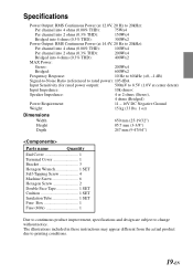
... Input Sensitivity (for rated power output): 500mV to 8.5V (1.0V at center detent) Input Impedance: 10k ohms< Speaker Impedance: 4 or 2 ohms (Stereo), 4 ohms (Bridged) Power Requirement: 11 - 16V DC Negative Ground Weight: 15 kg (33 lbs. 1 oz) Dimensions Width Height Depth 650 mm (25-19/32") 85.7 mm (3-3/8") 247 mm (9-47/64") Parts name Quantity End Cover 1 Terminal Cover 1 Bracket 3 Hexagon Wrench 1 SET Self-Tapping Screw 4 Machine Screw 6 Hexagon Screw...
... Input Sensitivity (for rated power output): 500mV to 8.5V (1.0V at center detent) Input Impedance: 10k ohms< Speaker Impedance: 4 or 2 ohms (Stereo), 4 ohms (Bridged) Power Requirement: 11 - 16V DC Negative Ground Weight: 15 kg (33 lbs. 1 oz) Dimensions Width Height Depth 650 mm (25-19/32") 85.7 mm (3-3/8") 247 mm (9-47/64") Parts name Quantity End Cover 1 Terminal Cover 1 Bracket 3 Hexagon Wrench 1 SET Self-Tapping Screw 4 Machine Screw 6 Hexagon Screw...
Owners Manual
Page 24
Service Care N For North American Customers IMPORTANT NOTICE This Amplifier has been type tested and found to comply with the limits for a Class B computing device in accordance with the specifications in Subpart J of Part 15 of America and Canada, please contact your dealer for information regarding warranty coverage. 20-EN This equipment generates and uses radio frequency energy, and...
Service Care N For North American Customers IMPORTANT NOTICE This Amplifier has been type tested and found to comply with the limits for a Class B computing device in accordance with the specifications in Subpart J of Part 15 of America and Canada, please contact your dealer for information regarding warranty coverage. 20-EN This equipment generates and uses radio frequency energy, and...


