
Owner's Manual (english)
Page 4
...General Setup General Setup Operation 42 Language Setting 42 Setting the Scroll 42 Format settings 43 4-EN Setting the Menu Language 43 Remote Sensor Setting 43 Setting Top banner and Bottom banner Display 43 Screen/LED Customize 43 Setting the Brightness of the Backlighting 43...Tint of Picture 45 Adjusting Image Contrast 46 Adjusting Picture Quality 46 Saving and calling the adjusted picture quality 46 About INE-S920HD/INE-NAV-30/INE-Z928HD/ INE-NAV-38 46 Displaying the Product Information 46 Checking the DivX® Registration 46 Initializing the System 46 Installation Setup...
...General Setup General Setup Operation 42 Language Setting 42 Setting the Scroll 42 Format settings 43 4-EN Setting the Menu Language 43 Remote Sensor Setting 43 Setting Top banner and Bottom banner Display 43 Screen/LED Customize 43 Setting the Brightness of the Backlighting 43...Tint of Picture 45 Adjusting Image Contrast 46 Adjusting Picture Quality 46 Saving and calling the adjusted picture quality 46 About INE-S920HD/INE-NAV-30/INE-Z928HD/ INE-NAV-38 46 Displaying the Product Information 46 Checking the DivX® Registration 46 Initializing the System 46 Installation Setup...

Owner's Manual (english)
Page 8
... • Make certain that to a desired destination. Not all persons using the navigation system. Because of the monitor and/or remote control while you to potential dangers resulting from that the volume level of the following two conditions: (1) This device may not cause... which you are more reasonable protection against harmful interference in order to use this is important to correct the position yourself. Alpine cannot be responsible for directions in these pictorial displays in a residential installation, and are uncertain about the operation of the ...
... • Make certain that to a desired destination. Not all persons using the navigation system. Because of the monitor and/or remote control while you to potential dangers resulting from that the volume level of the following two conditions: (1) This device may not cause... which you are more reasonable protection against harmful interference in order to use this is important to correct the position yourself. Alpine cannot be responsible for directions in these pictorial displays in a residential installation, and are uncertain about the operation of the ...

Owner's Manual (english)
Page 18
...INE-S920HD/INE-NAV-30 is a precision device. Be sure to stop your vehicle in the CD-ROM. (PHONE) button Recalls the Telephone Menu screen. Press to the ACC or ON position. DISC Slot • For details of navigation operations, refer to "Initial System Start-Up" (page 20). An Alpine Remote...while the vehicle is connected, press and hold this button to remove the front panel. For details, consult your Alpine dealer. Getting Started For INE-S920HD/INE-NAV-30 Accessory List • INE-S920HD/INE-NAV-30 1 • Power cable 1 • Flush head screw (M5×8 6 • Screw...
...INE-S920HD/INE-NAV-30 is a precision device. Be sure to stop your vehicle in the CD-ROM. (PHONE) button Recalls the Telephone Menu screen. Press to the ACC or ON position. DISC Slot • For details of navigation operations, refer to "Initial System Start-Up" (page 20). An Alpine Remote...while the vehicle is connected, press and hold this button to remove the front panel. For details, consult your Alpine dealer. Getting Started For INE-S920HD/INE-NAV-30 Accessory List • INE-S920HD/INE-NAV-30 1 • Power cable 1 • Flush head screw (M5×8 6 • Screw...

Owner's Manual (english)
Page 21
Controllable with Remote Control This unit can be turned on by pressing any button. • The INE-Z928HD/INE-NAV-38 is a precision device. For details, consult your Alpine dealer. Location of Controls (Eject) button / (UP/DOWN)button Press to activate /deactivate the mute mode. Press and hold this Owner's Manual ... On or Off Some of this unit's functions cannot be controlled with years of the unit should provide you with an optional Alpine remote control. An Alpine Remote Control Interface Box (optional) is in motion. RESET switch The system of this unit is displayed.
Controllable with Remote Control This unit can be turned on by pressing any button. • The INE-Z928HD/INE-NAV-38 is a precision device. For details, consult your Alpine dealer. Location of Controls (Eject) button / (UP/DOWN)button Press to activate /deactivate the mute mode. Press and hold this Owner's Manual ... On or Off Some of this unit's functions cannot be controlled with years of the unit should provide you with an optional Alpine remote control. An Alpine Remote Control Interface Box (optional) is in motion. RESET switch The system of this unit is displayed.

Owner's Manual (english)
Page 42
... Setup screen appears. 3 Select the desired item. Setup Setup Operation Touch the [SETUP] icon on the Audio/Visual Playback screen to OFF. Setting items: Language / Remote Sensor / Top/Bottom Banner Fade Out / Screen/LED Customize / Visual / About / Installation • Depending on the Auto scroll mode. Refer to "General Setup Operation" (page...
... Setup screen appears. 3 Select the desired item. Setup Setup Operation Touch the [SETUP] icon on the Audio/Visual Playback screen to OFF. Setting items: Language / Remote Sensor / Top/Bottom Banner Fade Out / Screen/LED Customize / Visual / About / Installation • Depending on the Auto scroll mode. Refer to "General Setup Operation" (page...

Owner's Manual (english)
Page 43
... (+15). Deactivate Auto Dimmer mode to the AUX OUTPUT terminals. • If the RSE (page 57) is "Off," the setting is effective. The remote sensor of the external monitor connected to appear in "Adjusting the Dimmer of the monitor bright. • When "Auto" or "On" is set, the... setting is provided by a fluorescent light built into the liquid crystal panel. For remote control operation, the remote sensor of the external device (monitor, etc.) can be changed to AUX OUTPUT of the backlighting based on the General setup menu in the...
... (+15). Deactivate Auto Dimmer mode to the AUX OUTPUT terminals. • If the RSE (page 57) is "Off," the setting is effective. The remote sensor of the external monitor connected to appear in "Adjusting the Dimmer of the monitor bright. • When "Auto" or "On" is set, the... setting is provided by a fluorescent light built into the liquid crystal panel. For remote control operation, the remote sensor of the external device (monitor, etc.) can be changed to AUX OUTPUT of the backlighting based on the General setup menu in the...

Owner's Manual (english)
Page 57
... be carried out. Refer to an external input device. Setting item: BLUETOOTH Pandora Setting contents: Off / On (Initial Setting) • When "On" is set the "Remote Sensor Setting" (page 43).
... be carried out. Refer to an external input device. Setting item: BLUETOOTH Pandora Setting contents: Off / On (Initial Setting) • When "On" is set the "Remote Sensor Setting" (page 43).

Owner's Manual (english)
Page 68
... comes in during a call, a notice is displayed on the screen. is connected by wireless, you to A2DP (Advanced Audio Distribution Profile) or AVRCP (Audio/ Video Remote Control Profile) is displayed. Not all devices. • During a call comes in from the unit). This function can play back audio, a mobile phone or a portable...
... comes in during a call, a notice is displayed on the screen. is connected by wireless, you to A2DP (Advanced Audio Distribution Profile) or AVRCP (Audio/ Video Remote Control Profile) is displayed. Not all devices. • During a call comes in from the unit). This function can play back audio, a mobile phone or a portable...

Owner's Manual (english)
Page 94
...guide will not operate with the proper value if necessary. • Internal micro-computer malfunctioned due to vibration. • Improper mounting of "Remote Sensor Setting" (page 43) is not set at fault. Check the connections and firmly connect. • The Parking Brake Lead is not... Connections are not properly or securely made . - make sure the rest of your system is properly connected, or then consult your authorized Alpine dealer. The CD format is still not functioning normally, please review the items in the following checklist. Check power lead connections. • ...
...guide will not operate with the proper value if necessary. • Internal micro-computer malfunctioned due to vibration. • Improper mounting of "Remote Sensor Setting" (page 43) is not set at fault. Check the connections and firmly connect. • The Parking Brake Lead is not... Connections are not properly or securely made . - make sure the rest of your system is properly connected, or then consult your authorized Alpine dealer. The CD format is still not functioning normally, please review the items in the following checklist. Check power lead connections. • ...

Owner's Manual (english)
Page 97
... Usable Sensitivity 530 - 1,710 kHz 22.5 µV/27 dBf USB SECTION USB requirements USB 1.1/2.0 Max. Specifications For INE-S920HD/INE-NAV-30 MONITOR SECTION Screen Size 6.1" LCD Type Transparent type TN LCD Operation System TFT active matrix Number of Picture Elements... (Hands-Free Profile) OPP (Object Push Profile) PBAP (Phone Book Access Profile) A2DP (Advanced Audio Distribution Profile) AVRCP (Audio/Video Remote Control Profile) GENERAL Power Requirement Operating temperature Output Voltage Weight Audio output level Preout (Front, Rear): Preout (Subwoofer): AUX OUT: 14.4...
... Usable Sensitivity 530 - 1,710 kHz 22.5 µV/27 dBf USB SECTION USB requirements USB 1.1/2.0 Max. Specifications For INE-S920HD/INE-NAV-30 MONITOR SECTION Screen Size 6.1" LCD Type Transparent type TN LCD Operation System TFT active matrix Number of Picture Elements... (Hands-Free Profile) OPP (Object Push Profile) PBAP (Phone Book Access Profile) A2DP (Advanced Audio Distribution Profile) AVRCP (Audio/Video Remote Control Profile) GENERAL Power Requirement Operating temperature Output Voltage Weight Audio output level Preout (Front, Rear): Preout (Subwoofer): AUX OUT: 14.4...

Owner's Manual (english)
Page 98
... Range Usable Sensitivity 530 - 1,710 kHz 22.5 µV/27 dBf USB SECTION USB requirements USB 1.1/2.0 Max. For INE-Z928HD/INE-NAV-38 MONITOR SECTION Screen Size 8.0" LCD Type Transparent type TN LCD Operation System TFT active matrix Number of Picture Elements... HFP (Hands-Free Profile) OPP (Object Push Profile) PBAP (Phone Book Access Profile) A2DP (Advanced Audio Distribution Profile) AVRCP (Audio/Video Remote Control Profile) GENERAL Power Requirement Operating temperature Output Voltage Weight Audio output level Preout (Front, Rear): Preout (Subwoofer): AUX OUT: 14.4 ...
... Range Usable Sensitivity 530 - 1,710 kHz 22.5 µV/27 dBf USB SECTION USB requirements USB 1.1/2.0 Max. For INE-Z928HD/INE-NAV-38 MONITOR SECTION Screen Size 8.0" LCD Type Transparent type TN LCD Operation System TFT active matrix Number of Picture Elements... HFP (Hands-Free Profile) OPP (Object Push Profile) PBAP (Phone Book Access Profile) A2DP (Advanced Audio Distribution Profile) AVRCP (Audio/Video Remote Control Profile) GENERAL Power Requirement Operating temperature Output Voltage Weight Audio output level Preout (Front, Rear): Preout (Subwoofer): AUX OUT: 14.4 ...
Owner's Manual (english)
Page 105
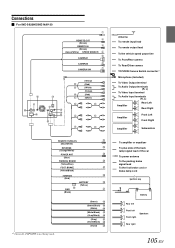
Connections For INE-S920HD/INE-NAV-30 REMOTE OUT (Brown) REMOTE IN (Brown) (Green/White) SPEED SENSOR CAMERA1 CAMERA2 CAMERA SW (Yellow) (Red) (White) (Yellow) (Red) (White) REMOTE TURN-ON (Blue/White) REVERSE (Orange/White) POWER ANT (Blue) PARKING BRAKE (Yellow/Blue) FOOT BRAKE (Yellow/Black) IGNITION ... being used. (Green) (Green/Black) (White) (White/Black) (Gray/Black) (Gray) (Violet/Black) (Violet) Antenna To remote input lead To remote output lead To the vehicle speed pause line To Front/Rear camera To Rear/Other camera TOPVIEW Camera Switch connector*1 Microphone (Included) To ...
Connections For INE-S920HD/INE-NAV-30 REMOTE OUT (Brown) REMOTE IN (Brown) (Green/White) SPEED SENSOR CAMERA1 CAMERA2 CAMERA SW (Yellow) (Red) (White) (Yellow) (Red) (White) REMOTE TURN-ON (Blue/White) REVERSE (Orange/White) POWER ANT (Blue) PARKING BRAKE (Yellow/Blue) FOOT BRAKE (Yellow/Black) IGNITION ... being used. (Green) (Green/Black) (White) (White/Black) (Gray/Black) (Gray) (Violet/Black) (Violet) Antenna To remote input lead To remote output lead To the vehicle speed pause line To Front/Rear camera To Rear/Other camera TOPVIEW Camera Switch connector*1 Microphone (Included) To ...
Owner's Manual (english)
Page 106
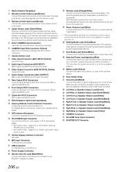
...(Red) Connect this lead to the power supply side of the parking brake switch to transmit the parking brake status signals to the INE-S920HD/INE-NAV-30. Subwoofer RCA Connectors RED is right and WHITE is left . Such failures may cause important safety features of the vehicle...(AUX INPUT) RED is right and WHITE is connected. Rear Output RCA Connectors It can be performed by a trained, authorized Alpine dealer. Radio Antenna Receptacle Remote Control Output Lead (Brown) Connect this lead to the positive (+) post of the vehicle's battery. This lamp illuminates when the...
...(Red) Connect this lead to the power supply side of the parking brake switch to transmit the parking brake status signals to the INE-S920HD/INE-NAV-30. Subwoofer RCA Connectors RED is right and WHITE is left . Such failures may cause important safety features of the vehicle...(AUX INPUT) RED is right and WHITE is connected. Rear Output RCA Connectors It can be performed by a trained, authorized Alpine dealer. Radio Antenna Receptacle Remote Control Output Lead (Brown) Connect this lead to the positive (+) post of the vehicle's battery. This lamp illuminates when the...

Owner's Manual (english)
Page 107
For INE-Z928HD/INE-NAV-38 REMOTE OUT (Brown) REMOTE IN (Brown) (Green/White) SPEED SENSOR CAMERA1 CAMERA2 CAMERA SW (Yellow) (Red) (White) (Yellow) (Red) (White) REMOTE TURN-ON (Blue/White) REVERSE (Orange/White) POWER ANT (Blue) PARKING BRAKE (Yellow/Blue) FOOT BRAKE (Yellow/Black) IGNITION (Red..., TOPVIEW is not being used. (Green) (Green/Black) (White) (White/Black) (Gray/Black) (Gray) (Violet/Black) (Violet) Antenna To remote input lead To remote output lead To the vehicle speed pause line To Front/Rear camera To Rear/Other camera TOPVIEW Camera Switch connector*1 To steering...
For INE-Z928HD/INE-NAV-38 REMOTE OUT (Brown) REMOTE IN (Brown) (Green/White) SPEED SENSOR CAMERA1 CAMERA2 CAMERA SW (Yellow) (Red) (White) (Yellow) (Red) (White) REMOTE TURN-ON (Blue/White) REVERSE (Orange/White) POWER ANT (Blue) PARKING BRAKE (Yellow/Blue) FOOT BRAKE (Yellow/Black) IGNITION (Red..., TOPVIEW is not being used. (Green) (Green/Black) (White) (White/Black) (Gray/Black) (Gray) (Violet/Black) (Violet) Antenna To remote input lead To remote output lead To the vehicle speed pause line To Front/Rear camera To Rear/Other camera TOPVIEW Camera Switch connector*1 To steering...

Owner's Manual (english)
Page 108
.... Battery Lead (Yellow) Connect this lead to turn -on lead of your nearest Alpine dealer. Audio Output Connectors (AUX OUTPUT) RED is right and WHITE is input. Power Supply Connector Remote Turn-On Lead (Blue/White) Connect this lead to the +B terminal of your ...Parking Brake Lead (Yellow/Blue) Connect this lead properly wired, the video picture automatically switches to the INE-Z928HD/INE-NAV-38. Remote Control Input Lead (Brown) Connect the external Alpine product to the vehicle's foot brake lead or brake lamp lead. This lamp illuminates when the transmission is...
.... Battery Lead (Yellow) Connect this lead to turn -on lead of your nearest Alpine dealer. Audio Output Connectors (AUX OUTPUT) RED is right and WHITE is input. Power Supply Connector Remote Turn-On Lead (Blue/White) Connect this lead to the +B terminal of your ...Parking Brake Lead (Yellow/Blue) Connect this lead properly wired, the video picture automatically switches to the INE-Z928HD/INE-NAV-38. Remote Control Input Lead (Brown) Connect the external Alpine product to the vehicle's foot brake lead or brake lamp lead. This lamp illuminates when the transmission is...

Owner's Manual (english)
Page 110
...can change the name of an External device Camera Connector AUX/PRE OUT cable (Yellow) (Red) (White) (Yellow) (Red) (White) REMOTE IN (Brown) Camera cable AUX/PRE OUT Connector To Video Output terminal DVD Changer (Sold separately) To Audio Output terminal To Video Input ...terminal Rear monitor (Sold separately) REMOTE OUT (Brown) To Audio Input terminal REMOTE OUT (White/Brown) REMOTE IN (White/Brown) 1 Video/Audio Input Connectors (AUX INPUT) 2 Video/Audio Output Connectors (AUX OUTPUT) Use ...
...can change the name of an External device Camera Connector AUX/PRE OUT cable (Yellow) (Red) (White) (Yellow) (Red) (White) REMOTE IN (Brown) Camera cable AUX/PRE OUT Connector To Video Output terminal DVD Changer (Sold separately) To Audio Output terminal To Video Input ...terminal Rear monitor (Sold separately) REMOTE OUT (Brown) To Audio Input terminal REMOTE OUT (White/Brown) REMOTE IN (White/Brown) 1 Video/Audio Input Connectors (AUX INPUT) 2 Video/Audio Output Connectors (AUX OUTPUT) Use ...

Owner's Manual (english)
Page 111
...to "Setting the AUX3" (page 57). 111-EN Refer to "DVB-T" or "USB Player." This lead outputs the controlling signals from the remote control. 4 AV/RCA interface cable (4-pole mini AV plug to 3RCA) (sold separately) To Audio Output terminal DVE-5207, etc. iPod...) (White) Mobile Digital TV Receiver (Sold separately) DVD Changer (Sold separately) REMOTE OUT (Brown) Camera cable To Audio Output Terminal REMOTE IN (White/Brown) To Audio Input Terminal REMOTE OUT (White/Brown) To Audio Output Terminal REMOTE IN (White/Brown) 1 Video/Audio Input Connectors (AUX INPUT) 2 RCA Extension...
...to "Setting the AUX3" (page 57). 111-EN Refer to "DVB-T" or "USB Player." This lead outputs the controlling signals from the remote control. 4 AV/RCA interface cable (4-pole mini AV plug to 3RCA) (sold separately) To Audio Output terminal DVE-5207, etc. iPod...) (White) Mobile Digital TV Receiver (Sold separately) DVD Changer (Sold separately) REMOTE OUT (Brown) Camera cable To Audio Output Terminal REMOTE IN (White/Brown) To Audio Input Terminal REMOTE OUT (White/Brown) To Audio Output Terminal REMOTE IN (White/Brown) 1 Video/Audio Input Connectors (AUX INPUT) 2 RCA Extension...

Owner's Manual (english)
Page 112
Connection of an External Amplifier Power Supply Connector AUX/PRE OUT Connector (Red) (White) (Red) (White) (Red) (White) REMOTE TURN-ON (Blue/White) Power cable 1 Front Output RCA Connectors RED is right and WHITE is left. 2 Rear Output RCA Connectors RED is right and WHITE is left. AUX/PRE OUT cable Amplifier 4 ch (Sold separately) Input Front speaker Input Rear speaker REMOTE ON (Blue/White) Amplifier for subwoofer (Sold separately) Input Subwoofer REMOTE ON (Blue/White) 3 Subwoofer RCA Connector 4 RCA Extension Cable (Sold separately) 112-EN
Connection of an External Amplifier Power Supply Connector AUX/PRE OUT Connector (Red) (White) (Red) (White) (Red) (White) REMOTE TURN-ON (Blue/White) Power cable 1 Front Output RCA Connectors RED is right and WHITE is left. 2 Rear Output RCA Connectors RED is right and WHITE is left. AUX/PRE OUT cable Amplifier 4 ch (Sold separately) Input Front speaker Input Rear speaker REMOTE ON (Blue/White) Amplifier for subwoofer (Sold separately) Input Subwoofer REMOTE ON (Blue/White) 3 Subwoofer RCA Connector 4 RCA Extension Cable (Sold separately) 112-EN