Owners Manual
Page 2
Contents Operating Instructions WARNING WARNING 2 CAUTION 3 PRECAUTIONS 3 Getting Started Feature 4 Rear Camera Operation Turning the Rear Camera On and Off 5 Changing the Rear Image Configuration .......... 5 Front Camera Operation Turning the Front Camera On and Off 6 Changing the Front Image Configuration ......... 6 Installation and Connections Mounting the Rear Camera (HCE-C200R) ...... 7 Mounting the Front Camera (HCE-C200F) (If HCE-C200F is purchased 10 Connections 11 System Example 12 Confirmation 14 Information Specifications 15 ENGLISH 1-EN
Contents Operating Instructions WARNING WARNING 2 CAUTION 3 PRECAUTIONS 3 Getting Started Feature 4 Rear Camera Operation Turning the Rear Camera On and Off 5 Changing the Rear Image Configuration .......... 5 Front Camera Operation Turning the Front Camera On and Off 6 Changing the Front Image Configuration ......... 6 Installation and Connections Mounting the Rear Camera (HCE-C200R) ...... 7 Mounting the Front Camera (HCE-C200F) (If HCE-C200F is purchased 10 Connections 11 System Example 12 Confirmation 14 Information Specifications 15 ENGLISH 1-EN
Owners Manual
Page 4
...white) to the positive (+) of the rearview mirror. Return it to fall of other fitting. When connecting the HCE-C200R/HCE-C200F to your authorized Alpine dealer or the nearest Alpine Service Centre for rust-prevention, and should be able to use a mobile phone or wireless device near the ... means important instructions. Use of and cause accidents, injury, or damage to the car body. When in doubt, consult your HCE-C200R/HCE-C200F. This may cause parts to the cable insulation, which may damage this unit requires special technical skill and experience. This will prevent...
...white) to the positive (+) of the rearview mirror. Return it to fall of other fitting. When connecting the HCE-C200R/HCE-C200F to your authorized Alpine dealer or the nearest Alpine Service Centre for rust-prevention, and should be able to use a mobile phone or wireless device near the ... means important instructions. Use of and cause accidents, injury, or damage to the car body. When in doubt, consult your HCE-C200R/HCE-C200F. This may cause parts to the cable insulation, which may damage this unit requires special technical skill and experience. This will prevent...
Owners Manual
Page 5
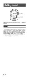
Getting Started ON/OFF MODE Operation is connected to the optional TOPVIEW FRONT CAMERA (HCE-C200F), you on the equipped monitor in the case of the TOPVIEW REAR CAMERA (HCE-C200R) and the equipped monitor. If the TOPVIEW REAR CAMERA is carried out by pressing the switch, or shifting the gear lever. Feature When reversing the car, you can also check conditions ahead of you can check behind and around the car with the assistance of a difficult-to-judge road or cross-roads. 4-EN
Getting Started ON/OFF MODE Operation is connected to the optional TOPVIEW FRONT CAMERA (HCE-C200F), you on the equipped monitor in the case of the TOPVIEW REAR CAMERA (HCE-C200R) and the equipped monitor. If the TOPVIEW REAR CAMERA is carried out by pressing the switch, or shifting the gear lever. Feature When reversing the car, you can also check conditions ahead of you can check behind and around the car with the assistance of a difficult-to-judge road or cross-roads. 4-EN
Owners Manual
Page 11
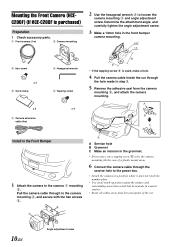
... camera 1 mounting 2. A B C Install to the Front Bumper 1 Attach the camera to loosen the camera mounting 2 and angle adjustment screw. Mounting the Front Camera (HCEC200F) (If HCE-C200F is used, make a hole. 4 Pull the camera cable inside the car through the service hole to the power box. • Attach the camera in a position...
... camera 1 mounting 2. A B C Install to the Front Bumper 1 Attach the camera to loosen the camera mounting 2 and angle adjustment screw. Mounting the Front Camera (HCEC200F) (If HCE-C200F is used, make a hole. 4 Pull the camera cable inside the car through the service hole to the power box. • Attach the camera in a position...
Owners Manual
Page 12
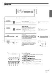
... signal lead of the monitor or navigation. 2 OTHER CAMERA Terminal Not used. 3 FRONT CAMERA Terminal Connect this to the front camera (HCE-C200F) 4 REAR CAMERA Terminal Connect this to the rear camera (HCE-C200R) 5 Switch Terminal Connect this lead to a metal part of the car's reverse lamp that ---- Make sure the connection is made...
... signal lead of the monitor or navigation. 2 OTHER CAMERA Terminal Not used. 3 FRONT CAMERA Terminal Connect this to the front camera (HCE-C200F) 4 REAR CAMERA Terminal Connect this to the rear camera (HCE-C200R) 5 Switch Terminal Connect this lead to a metal part of the car's reverse lamp that ---- Make sure the connection is made...
Owners Manual
Page 13
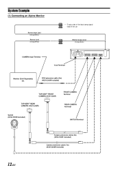
RCA extension cable (2m) (HCE-C200R included) TOPVIEW FRONT CAMERA (HCE-C200F) TOPVIEW REAR CAMERA (HCE-C200R) FRONT CAMERA Terminal REAR CAMERA Terminal Switch (HCE-C200R included) SWITCH Terminal Camera extension cable (4m) (HCE-C200F included) Camera extension cable (7m) (HCE-C200R included) 12-EN System Example (1) Connecting an Alpine Monitor Reverse Input Lead (Orange/White) Reverse Lead (Orange/White) ---- To plus...
RCA extension cable (2m) (HCE-C200R included) TOPVIEW FRONT CAMERA (HCE-C200F) TOPVIEW REAR CAMERA (HCE-C200R) FRONT CAMERA Terminal REAR CAMERA Terminal Switch (HCE-C200R included) SWITCH Terminal Camera extension cable (4m) (HCE-C200F included) Camera extension cable (7m) (HCE-C200R included) 12-EN System Example (1) Connecting an Alpine Monitor Reverse Input Lead (Orange/White) Reverse Lead (Orange/White) ---- To plus...
Owners Manual
Page 14
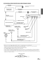
... (HCE-C200F) TOPVIEW REAR CAMERA (HCE-C200R) Switch (HCE-C200R included) FRONT CAMERA Terminal REAR CAMERA Terminal SWITCH Terminal Camera extension cable (4m) (HCE-C200F included) Camera extension cable (7m) (HCE-C200R included...as to avoid hot parts. • The front view camera (HCE-C200F) and rear view camera (HCE-C200R) are designed to be identified by their bottom labels. •...OUT Terminal Head Unit (Sold Separately) CAMERA Input Terminal RCA extension cable (2m) (HCE-C200R included) IVA-D310 series, IVA-W200 series, etc. When disconnecting the water-proof connector...
... (HCE-C200F) TOPVIEW REAR CAMERA (HCE-C200R) Switch (HCE-C200R included) FRONT CAMERA Terminal REAR CAMERA Terminal SWITCH Terminal Camera extension cable (4m) (HCE-C200F included) Camera extension cable (7m) (HCE-C200R included...as to avoid hot parts. • The front view camera (HCE-C200F) and rear view camera (HCE-C200R) are designed to be identified by their bottom labels. •...OUT Terminal Head Unit (Sold Separately) CAMERA Input Terminal RCA extension cable (2m) (HCE-C200R included) IVA-D310 series, IVA-W200 series, etc. When disconnecting the water-proof connector...
Owners Manual
Page 16
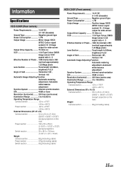
Information Specifications HCE-C200R (Rear camera) Power Requirements 14.4V DC (11-16V allowable) Ground Type Negative ground type Power Consumption 1.7W Output Image Mirror image, VBCS (NTSC Colour ... projection) Switch section 29 x 38.5 x 13.6mm (1-1/8" x 1-1/2" x 17/32") Weight Camera section 80g (including cable) Power section 270g (including cable) Switch section 50g (including cable) HCE-C200F (Front camera) Power Requirements 14.4V DC (11-16V allowable) Ground Type Negative ground type Power Consumption 1.7W Output Image Positive image, VBCS (NTSC Colour...
Information Specifications HCE-C200R (Rear camera) Power Requirements 14.4V DC (11-16V allowable) Ground Type Negative ground type Power Consumption 1.7W Output Image Mirror image, VBCS (NTSC Colour ... projection) Switch section 29 x 38.5 x 13.6mm (1-1/8" x 1-1/2" x 17/32") Weight Camera section 80g (including cable) Power section 270g (including cable) Switch section 50g (including cable) HCE-C200F (Front camera) Power Requirements 14.4V DC (11-16V allowable) Ground Type Negative ground type Power Consumption 1.7W Output Image Positive image, VBCS (NTSC Colour...
