

Getting Started Guide
Page 2
...Rules. All other brand and product names are registered trademarks of Compagnie Financiére Alcatel, Paris, France. The functionality described in part without notice. Omni Switch/Router™, SwitchExpertSM, the Xylan logo are designed to maintain and maximize your company... service delivery partners. You'll also receive regular software updates to provide Copyright© 2006 by Alcatel Internetworking, Inc. These limits are trademarks of Alcatel Internetworking, Inc. Additionally, with the limits for Class A digital device pursuant to change without the...
...Rules. All other brand and product names are registered trademarks of Compagnie Financiére Alcatel, Paris, France. The functionality described in part without notice. Omni Switch/Router™, SwitchExpertSM, the Xylan logo are designed to maintain and maximize your company... service delivery partners. You'll also receive regular software updates to provide Copyright© 2006 by Alcatel Internetworking, Inc. These limits are trademarks of Alcatel Internetworking, Inc. Additionally, with the limits for Class A digital device pursuant to change without the...

Getting Started Guide
Page 7
...: Faseroptikanschlüsse - Check it to any input voltage within the range marked on the cable) against the following safety information carefully before installing the switch: WARNING: Installation and removal of 0.75 mm2 IEC-320 receptacle Male plug rated 10A, 250V The unit automatically matches the connected input voltage. Avertissment: Ports...
...: Faseroptikanschlüsse - Check it to any input voltage within the range marked on the cable) against the following safety information carefully before installing the switch: WARNING: Installation and removal of 0.75 mm2 IEC-320 receptacle Male plug rated 10A, 250V The unit automatically matches the connected input voltage. Avertissment: Ports...

Getting Started Guide
Page 8
... comply with Section 107-2-D1, Standard DK2-1a or DK2-5a. Veuillez lire à fond l'information de la sécurité suivante avant d'installer le Switch: AVERTISSEMENT: L'installation et la dépose de ce groupe doivent être confiés à un viii No. 18 AWG - Europe The supply plug must...
... comply with Section 107-2-D1, Standard DK2-1a or DK2-5a. Veuillez lire à fond l'information de la sécurité suivante avant d'installer le Switch: AVERTISSEMENT: L'installation et la dépose de ce groupe doivent être confiés à un viii No. 18 AWG - Europe The supply plug must...

Getting Started Guide
Page 11
... elektrische Gefahren zu vermeiden. xi Installation and removal of a Class 1 Laser Product and are compliant with RJ-45 connectors that conform to FCC standards. This switch uses lasers to a power outlet, connect the field ground lead on . The lasers are inherently eye safe in normal operation. However, you should never look...
... elektrische Gefahren zu vermeiden. xi Installation and removal of a Class 1 Laser Product and are compliant with RJ-45 connectors that conform to FCC standards. This switch uses lasers to a power outlet, connect the field ground lead on . The lasers are inherently eye safe in normal operation. However, you should never look...

Getting Started Guide
Page 13
... networking concepts. End of Product Life Span This product is manufactured in such a way as part of the switch's firmware, there is for the recovery and disposal of all management related features. Audience This guide is an online web-based help that ... forests. Related Publications The following publication gives specific information on how to operate and use the management functions of the switch: The OmniStack® 6200 User Guide Also, as to install the switch. Manufacturing Materials There are no hazardous nor ozone-depleting materials in the printing process are non-toxic.
... networking concepts. End of Product Life Span This product is manufactured in such a way as part of the switch's firmware, there is for the recovery and disposal of all management related features. Audience This guide is an online web-based help that ... forests. Related Publications The following publication gives specific information on how to operate and use the management functions of the switch: The OmniStack® 6200 User Guide Also, as to install the switch. Manufacturing Materials There are no hazardous nor ozone-depleting materials in the printing process are non-toxic.

Getting Started Guide
Page 15
...Backup Power Supply Power Supply Receptacles Features and Benefits Connectivity Expandability Performance Management Chapter 2: Installing the Switch Selecting a Site Ethernet Cabling Equipment Checklist Package Contents Optional Rack-Mounting Equipment Mounting Rack Mounting ... Auswählen Montage Chapter 3: Making Network Connections Connecting Network Devices Twisted-Pair Devices Cabling Guidelines Connecting to PCs, Servers, Hubs and Switches Network Wiring Connections Fiber Optic SFP Devices Connectivity Rules 1000BASE-T Cable Requirements 1-5 1-5 1-6 1-6 1-6 1-6 1-7 1-8 1-10 1-11 ...
...Backup Power Supply Power Supply Receptacles Features and Benefits Connectivity Expandability Performance Management Chapter 2: Installing the Switch Selecting a Site Ethernet Cabling Equipment Checklist Package Contents Optional Rack-Mounting Equipment Mounting Rack Mounting ... Auswählen Montage Chapter 3: Making Network Connections Connecting Network Devices Twisted-Pair Devices Cabling Guidelines Connecting to PCs, Servers, Hubs and Switches Network Wiring Connections Fiber Optic SFP Devices Connectivity Rules 1000BASE-T Cable Requirements 1-5 1-5 1-6 1-6 1-6 1-6 1-7 1-8 1-10 1-11 ...

Getting Started Guide
Page 16
Contents 1000 Mbps Gigabit Ethernet Collision Domain 100 Mbps Fast Ethernet Collision Domain 10 Mbps Ethernet Collision Domain Cable Labeling and Connection Records Appendix A: Troubleshooting Diagnosing Switch Indicators Power and Cooling Problems Installation In-Band Access Appendix B: Cables Twisted-Pair Cable and Pin Assignments 10BASE-T/100BASE-TX Pin Assignments 1000BASE-T Pin Assignments Fiber Standards Appendix C: Specifications Compliances Glossary Index 3-24 3-25 3-25 3-26 4-27 4-27 4-27 4-27 4-27 5-29 5-29 5-29 5-30 5-31 6-33 6-36 xvi
Contents 1000 Mbps Gigabit Ethernet Collision Domain 100 Mbps Fast Ethernet Collision Domain 10 Mbps Ethernet Collision Domain Cable Labeling and Connection Records Appendix A: Troubleshooting Diagnosing Switch Indicators Power and Cooling Problems Installation In-Band Access Appendix B: Cables Twisted-Pair Cable and Pin Assignments 10BASE-T/100BASE-TX Pin Assignments 1000BASE-T Pin Assignments Fiber Standards Appendix C: Specifications Compliances Glossary Index 3-24 3-25 3-25 3-26 4-27 4-27 4-27 4-27 4-27 5-29 5-29 5-29 5-30 5-31 6-33 6-36 xvi

Getting Started Guide
Page 17
Figures Front Panel ...1-6 Port LEDs ...1-8 Combo Port LEDs 1-8 System LEDs ...1-9 DC BPS Back Panel 1-11 AC BPS Back Panel 1-11 PoE BPS Back Panel 1-11 Power Supply Receptacle 1-11 RJ-45 Connections 2-14 Attaching the Brackets 2-15 Installing the Switch in a Rack 2-16 Attaching the Adhesive Feet 2-16 Inserting an SFP Transceiver into a Slot 2-17 Power Receptacle 2-18 Making Twisted-Pair Connections 3-21 Network Wiring Connections 3-22 Making LC Port Connections 3-23 RJ-45 Connector Pin Numbers 5-29 1
Figures Front Panel ...1-6 Port LEDs ...1-8 Combo Port LEDs 1-8 System LEDs ...1-9 DC BPS Back Panel 1-11 AC BPS Back Panel 1-11 PoE BPS Back Panel 1-11 Power Supply Receptacle 1-11 RJ-45 Connections 2-14 Attaching the Brackets 2-15 Installing the Switch in a Rack 2-16 Attaching the Adhesive Feet 2-16 Inserting an SFP Transceiver into a Slot 2-17 Power Receptacle 2-18 Making Twisted-Pair Connections 3-21 Network Wiring Connections 3-22 Making LC Port Connections 3-23 RJ-45 Connector Pin Numbers 5-29 1

Getting Started Guide
Page 21
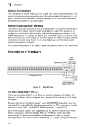
... two ports full-duplex Gigabit stacking. Ethernet based switch with 48 RJ-45 10/100Base-TX ports, two Gigabit combo uplink ports (with SFP or 10/100/1000Base-TX interfaces) and two ports full-duplex Gigabit stacking • OS-LS-6224P - Chapter 1: Introduction Overview The OmniStack® ...6200 series has nine platforms: • OS-LS-6212 - Ethernet based switch with 24 RJ-45 10/100Base-TX ports, two Gigabit combo uplink ports (with SFP...
... two ports full-duplex Gigabit stacking. Ethernet based switch with 48 RJ-45 10/100Base-TX ports, two Gigabit combo uplink ports (with SFP or 10/100/1000Base-TX interfaces) and two ports full-duplex Gigabit stacking • OS-LS-6224P - Chapter 1: Introduction Overview The OmniStack® ...6200 series has nine platforms: • OS-LS-6212 - Ethernet based switch with 24 RJ-45 10/100Base-TX ports, two Gigabit combo uplink ports (with SFP...
Getting Started Guide
Page 22
...) can be configured manually. 1-6 If a device connected to the User Guide. For a detailed description of the switch's advanced features, refer to one of -band), or you to configure or monitor the switch using Telnet, the on page B-30) Each of these ports does not support auto-negotiation, the communication mode... of that port can manage the switch through cables for "at 10 Mbps, 100 Mbps or 1000 Mbps, half or full duplex, and Fiber ports that allows you can be selected ...
...) can be configured manually. 1-6 If a device connected to the User Guide. For a detailed description of the switch's advanced features, refer to one of -band), or you to configure or monitor the switch using Telnet, the on page B-30) Each of these ports does not support auto-negotiation, the communication mode... of that port can manage the switch through cables for "at 10 Mbps, 100 Mbps or 1000 Mbps, half or full duplex, and Fiber ports that allows you can be selected ...

Getting Started Guide
Page 23
...der Gesamtsicherheit beachtet werden, das die maximale Umgebungstemperatur des Transceivers für den Betrieb nicht niedriger ist als die für dieses Produkts. The switch can function at a temperature that is disabled and cannot be configured to force the use an approved Laser Class 1 SFP transceiver. Der ...Glasfasertransceiver muß auch ein überprüftes Gerät der Laser Klasse 1 sein. 1-7 On the LS-OS-6224U, there are two RJ-45 ports, which are shared with two of the product. Note: When selecting a fiber SFP device, considering safety...
...der Gesamtsicherheit beachtet werden, das die maximale Umgebungstemperatur des Transceivers für den Betrieb nicht niedriger ist als die für dieses Produkts. The switch can function at a temperature that is disabled and cannot be configured to force the use an approved Laser Class 1 SFP transceiver. Der ...Glasfasertransceiver muß auch ein überprüftes Gerät der Laser Klasse 1 sein. 1-7 On the LS-OS-6224U, there are two RJ-45 ports, which are shared with two of the product. Note: When selecting a fiber SFP device, considering safety...

Getting Started Guide
Page 25
... Amber Off Flashing Green On Green On Amber On Green On Amber Off On Green Flashing Green On Amber Flashing Amber System Status LEDs Status Switch is connected and operating normally. The Backup Power Supply is off or failure. System initialization (Master unit). Power off or disconnected. System initialization (Slave unit...
... Amber Off Flashing Green On Green On Amber On Green On Amber Off On Green Flashing Green On Amber Flashing Amber System Status LEDs Status Switch is connected and operating normally. The Backup Power Supply is off or failure. System initialization (Master unit). Power off or disconnected. System initialization (Slave unit...
Getting Started Guide
Page 26
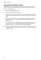
1 Introduction Setting Stacking/Standalone Modes The OS6200 switch provides Stacking and Standalone working modes. Wait until the required unit ID is selected. Press the Unit button with short intervals until the LED color ... to a Stacking mode. 4. Hold the Unit button until no port LED is in a stacking mode : 1. Releasing the button for backup or slave). 1-10 Reboot the Alcatel OS6200 switch. 2. Note: When the OS6200 is in stand-alone mode, the "stack" LED is off.If the...
1 Introduction Setting Stacking/Standalone Modes The OS6200 switch provides Stacking and Standalone working modes. Wait until the required unit ID is selected. Press the Unit button with short intervals until the LED color ... to a Stacking mode. 4. Hold the Unit button until no port LED is in a stacking mode : 1. Releasing the button for backup or slave). 1-10 Reboot the Alcatel OS6200 switch. 2. Note: When the OS6200 is in stand-alone mode, the "stack" LED is off.If the...
Getting Started Guide
Page 27
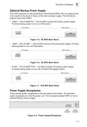
... cord. The receptacle labeled "BPS" is for the optional Backup Power Supply. Provides backup power to one OS LS-6200 PoE capable switch. Figure 1-8. Power Supply Receptacle 1-11 The U24 device support three kind of the switch. PoE BPS Back Panel Power Supply Receptacles There are two power receptacles on the rear panel of...
... cord. The receptacle labeled "BPS" is for the optional Backup Power Supply. Provides backup power to one OS LS-6200 PoE capable switch. Figure 1-8. Power Supply Receptacle 1-11 The U24 device support three kind of the switch. PoE BPS Back Panel Power Supply Receptacles There are two power receptacles on the rear panel of...
Getting Started Guide
Page 28
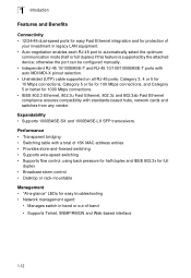
...; 12/24/48 dual-speed ports for easy Fast Ethernet integration and for easy troubleshooting • Network management agent: • Manages switch in-band or out-of your investment in legacy LAN equipment. • Auto-negotiation enables each RJ-45 port to automatically select the...3z and 802.3ab Fast Ethernet compliance ensures compatibility with a total of 16K MAC address entries • Provides store-and-forward switching • Supports wire-speed switching • Supports flow control, using back pressure for half duplex and IEEE 802.3x for full duplex • Broadcast storm ...
...; 12/24/48 dual-speed ports for easy Fast Ethernet integration and for easy troubleshooting • Network management agent: • Manages switch in-band or out-of your investment in legacy LAN equipment. • Auto-negotiation enables each RJ-45 port to automatically select the...3z and 802.3ab Fast Ethernet compliance ensures compatibility with a total of 16K MAC address entries • Provides store-and-forward switching • Supports wire-speed switching • Supports flow control, using back pressure for half duplex and IEEE 802.3x for full duplex • Broadcast storm ...

Getting Started Guide
Page 29
... network wiring • Safe connections with no damaged cables, connectors or shields 2-13 Ethernet Cabling To ensure proper operation when installing the switch into a network, make sure that provides 100 to 240 VAC, 50 to 60 Hz, is powered from radio frequency interference emissions &#...8226; Electrical surge suppression • Separation of electrical wires (switch related or other sources of electrical interference, such as radios and transmitters. • Make sure that the unit is recommended. As with ...
... network wiring • Safe connections with no damaged cables, connectors or shields 2-13 Ethernet Cabling To ensure proper operation when installing the switch into a network, make sure that provides 100 to 240 VAC, 50 to 60 Hz, is powered from radio frequency interference emissions &#...8226; Electrical surge suppression • Separation of electrical wires (switch related or other sources of electrical interference, such as radios and transmitters. • Make sure that the unit is recommended. As with ...

Getting Started Guide
Page 30
...8226; Ethernet Cable Adapter • This Getting Started Guide • User Guide Optional Rack-Mounting Equipment If you plan to rack-mount the switch, be sure to be sure you plan to install in a rack-these are not included • A screwdriver (Phillips or flathead, depending ...on the type of screws used) 2-14 RJ-45 Connections Equipment Checklist After unpacking the switch, check the contents to have the following equipment available: • Mounting screws for each device you have received all other necessary installation equipment.
...8226; Ethernet Cable Adapter • This Getting Started Guide • User Guide Optional Rack-Mounting Equipment If you plan to rack-mount the switch, be sure to be sure you plan to install in a rack-these are not included • A screwdriver (Phillips or flathead, depending ...on the type of screws used) 2-14 RJ-45 Connections Equipment Checklist After unpacking the switch, check the contents to have the following equipment available: • Mounting screws for each device you have received all other necessary installation equipment.

Getting Started Guide
Page 31
...: Rack-mounted equipment should be mounted in the Bracket Mounting Kit. To rack-mount devices: 1. Attaching the Brackets 2-15 Rack Mounting Before rack mounting the switch, pay particular attention to the following factors: • Temperature: Since the temperature within the specified operating temperature range. (See page C-34.) • Mechanical Loading: Do...
...: Rack-mounted equipment should be mounted in the Bracket Mounting Kit. To rack-mount devices: 1. Attaching the Brackets 2-15 Rack Mounting Before rack mounting the switch, pay particular attention to the following factors: • Temperature: Since the temperature within the specified operating temperature range. (See page C-34.) • Mechanical Loading: Do...

Getting Started Guide
Page 32
Figure 2-3. Set the device on a flat surface near an AC power source, making sure there 2-16 Attaching the Adhesive Feet 2. Attach the four adhesive feet to a Power Source" at the end of the first switch. 2 Installing the Switch 2. Installing the Switch in any order. If installing a single switch only, turn to "Connecting to the bottom of this chapter. 4. Figure 2-4. If installing multiple switches, mount them in the rack, one below the other, in a Rack 3. Mount the device in the rack, using rack-mounting screws (not provided). Desktop or Shelf Mounting 1.
Figure 2-3. Set the device on a flat surface near an AC power source, making sure there 2-16 Attaching the Adhesive Feet 2. Attach the four adhesive feet to a Power Source" at the end of the first switch. 2 Installing the Switch 2. Installing the Switch in any order. If installing a single switch only, turn to "Connecting to the bottom of this chapter. 4. Figure 2-4. If installing multiple switches, mount them in the rack, one below the other, in a Rack 3. Mount the device in the rack, using rack-mounting screws (not provided). Desktop or Shelf Mounting 1.

Getting Started Guide
Page 33
...the transceiver with the optical connector facing outward and the slot connector facing down. Note that SFP transceivers are hot-swappable. If installing a single switch only, go to "Connecting to a Power Source" at the end of space on top of the device. 2-17 Slide the SFP transceiver ... they can only be powered off before removing a transceiver. 2 Connecting to a Power Source are at least two inches of this chapter. 4. The switch does not need to select an appropriate SFP transceiver type. 2. Insert the power cable plug directly into a Slot To install an SFP transceiver, do...
...the transceiver with the optical connector facing outward and the slot connector facing down. Note that SFP transceivers are hot-swappable. If installing a single switch only, go to "Connecting to a Power Source" at the end of space on top of the device. 2-17 Slide the SFP transceiver ... they can only be powered off before removing a transceiver. 2 Connecting to a Power Source are at least two inches of this chapter. 4. The switch does not need to select an appropriate SFP transceiver type. 2. Insert the power cable plug directly into a Slot To install an SFP transceiver, do...