
Quick Installation Guide
Page 2
... the equipment is operated in any form or by any means or used to make any derivative such as translation, transformation, or adaptation without permission from Phoebe Micro, Inc. Preface FCC Warning This device ...user's manual, may cause interference in which case the user may be reproduced in a commercial environment. Trademarks Copyright © 2011 Airlink101® Airlink101® is a Class A product. This equipment generates, uses and can radiate radio frequency energy and, if not installed and used in accordance with limits for a Class a digital device, pursuant to Part...
... the equipment is operated in any form or by any means or used to make any derivative such as translation, transformation, or adaptation without permission from Phoebe Micro, Inc. Preface FCC Warning This device ...user's manual, may cause interference in which case the user may be reproduced in a commercial environment. Trademarks Copyright © 2011 Airlink101® Airlink101® is a Class A product. This equipment generates, uses and can radiate radio frequency energy and, if not installed and used in accordance with limits for a Class a digital device, pursuant to Part...

Quick Installation Guide
Page 3
.../10000Mbps Green Switch, and "switch" (first letter lower case) refers to other Ethernet switches. 1.1 Hardware Interface • 24-Port 10/100/1000Mbps auto-negotiation RJ45 Ports • All ports support auto MDI/MDIX, no need to use cross-over cables 2 Purpose This Quick Installation Guide tells you to extend your Ethernet network. Terms/Usage In this manual, the term "Switch" (first letter upper case) refers to your network structure quickly and reliably. It is an easy-installed network switch...
.../10000Mbps Green Switch, and "switch" (first letter lower case) refers to other Ethernet switches. 1.1 Hardware Interface • 24-Port 10/100/1000Mbps auto-negotiation RJ45 Ports • All ports support auto MDI/MDIX, no need to use cross-over cables 2 Purpose This Quick Installation Guide tells you to extend your Ethernet network. Terms/Usage In this manual, the term "Switch" (first letter upper case) refers to your network structure quickly and reliably. It is an easy-installed network switch...

Quick Installation Guide
Page 4
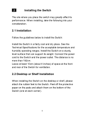
Figure 1-1 Front Panel view of the switch and the network (see Section 1.2.3). 3 These ports also support automatic MDI/MDI-X crossover detection, giving true "plug and play" capability. • LED Indicators: Comprehensive LED indicators display the status of the Switch • 10/100/1000Mbps Ports (Port 1~24): These ports support 10/100/1000Mbps, and can operate in Half/Full Duplex transfer modes. The figure below shows the front panel of LED indicators, and 24 10/100/1000Mbps ports. 1.2 Panel 1.2.1 Front Panel The front panel of the Switch consists of the Switch.
Figure 1-1 Front Panel view of the switch and the network (see Section 1.2.3). 3 These ports also support automatic MDI/MDI-X crossover detection, giving true "plug and play" capability. • LED Indicators: Comprehensive LED indicators display the status of the Switch • 10/100/1000Mbps Ports (Port 1~24): These ports support 10/100/1000Mbps, and can operate in Half/Full Duplex transfer modes. The figure below shows the front panel of LED indicators, and 24 10/100/1000Mbps ports. 1.2 Panel 1.2.1 Front Panel The front panel of the Switch consists of the Switch.
Quick Installation Guide
Page 5
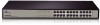
1.2.2 Rear Panel Figure 1-2 Rear Panel view of the switch 4 Figure 1-3 Front Panel view of the Switch • AC Power Connector: Supports AC 100~240V, 50~60Hz. NOTICE: Do not cover or put anything on and surrounding the switch while the Switch is operating. 1.2.3 LED indicators information The front panel LEDs provide instant status feedback and help monitoring and troubleshooting when needed.
1.2.2 Rear Panel Figure 1-2 Rear Panel view of the switch 4 Figure 1-3 Front Panel view of the Switch • AC Power Connector: Supports AC 100~240V, 50~60Hz. NOTICE: Do not cover or put anything on and surrounding the switch while the Switch is operating. 1.2.3 LED indicators information The front panel LEDs provide instant status feedback and help monitoring and troubleshooting when needed.

Quick Installation Guide
Page 6
• POWER: Power Indicator LED POWER Color Green Solid The Switch is power-on Status Blinking N/A Off No power • Port 1~24 10/100/1000Mbps Status LEDs LED LINK/ ACT 10/100M LED LINK/ ACT 1000M Color Green Color Green Solid The respective port is successfully connected to the 10/100Mbps Ethernet network Solid The respective port is connected to the 1000Mbps Ethernet network Status Blinking The port is transmitting or receiving data at 10/100Mbps Status Blinking The port is transmitting or receiving data at above 100Mbps Off No link Off No link 5
• POWER: Power Indicator LED POWER Color Green Solid The Switch is power-on Status Blinking N/A Off No power • Port 1~24 10/100/1000Mbps Status LEDs LED LINK/ ACT 10/100M LED LINK/ ACT 1000M Color Green Color Green Solid The respective port is successfully connected to the 10/100Mbps Ethernet network Solid The respective port is connected to the 1000Mbps Ethernet network Status Blinking The port is transmitting or receiving data at 10/100Mbps Status Blinking The port is transmitting or receiving data at above 100Mbps Off No link Off No link 5
Quick Installation Guide
Page 7
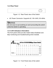
....3x Flow Control Network Cables • Ethernet (10Base-T): Cables: 2-pair UTP Cat. 3, 4, 5, Twisted Pair (UTP). Up to 100m • Fast and Giga Ethernet (100/1000Base-T): 2-pair UTP Cat. 5, Twisted Pair (UTP). Up to 100m Ports • 24 x 10/100/1000Mbps Auto-Negotiation RJ45 Port Access Method • CSMA/CD Transmission Method • Store and Forward MAC Address Table • 16K Jumbo Frame • 9216-byte jumbo packet length forwarding at wire speed 6
....3x Flow Control Network Cables • Ethernet (10Base-T): Cables: 2-pair UTP Cat. 3, 4, 5, Twisted Pair (UTP). Up to 100m • Fast and Giga Ethernet (100/1000Base-T): 2-pair UTP Cat. 5, Twisted Pair (UTP). Up to 100m Ports • 24 x 10/100/1000Mbps Auto-Negotiation RJ45 Port Access Method • CSMA/CD Transmission Method • Store and Forward MAC Address Table • 16K Jumbo Frame • 9216-byte jumbo packet length forwarding at wire speed 6

Quick Installation Guide
Page 8
Half/Full-Duplex • Fast Ethernet: 100/200Mbps - Half/Full Duplex Physical and Environmental • Power Input: 100~240V AC, 50~60Hz • Operation Temperature: 0 °C ~ 40°C • Storage Temperature: -20°C ~ 70°C • Humidity: 5% ~ 90% RH, non-condensing 7 Half/Full Duplex • Giga Ethernet 1000/2000Mbps - Data Transfer Rate** • Ethernet: 10/20Mbps -
Half/Full-Duplex • Fast Ethernet: 100/200Mbps - Half/Full Duplex Physical and Environmental • Power Input: 100~240V AC, 50~60Hz • Operation Temperature: 0 °C ~ 40°C • Storage Temperature: -20°C ~ 70°C • Humidity: 5% ~ 90% RH, non-condensing 7 Half/Full Duplex • Giga Ethernet 1000/2000Mbps - Data Transfer Rate** • Ethernet: 10/20Mbps -
Quick Installation Guide
Page 9
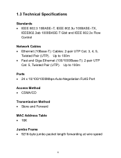
... humidity operating ranges. Connect the power cord to install the Switch: Install the Switch in a fairly cool and dry place. See the Technical Specifications for ventilation. 2.2 Desktop or Shelf Installation When installing the Switch on a sturdy, level surface that can support its performance. Install the Switch on the desktop or shelf, please attach the rubber feet to the Switch. 2 Installing the Switch The site where you...
... humidity operating ranges. Connect the power cord to install the Switch: Install the Switch in a fairly cool and dry place. See the Technical Specifications for ventilation. 2.2 Desktop or Shelf Installation When installing the Switch on a sturdy, level surface that can support its performance. Install the Switch on the desktop or shelf, please attach the rubber feet to the Switch. 2 Installing the Switch The site where you...

Quick Installation Guide
Page 10
The switch's power supply will adjust to 240V AC, 50 ~ 60Hz power source. The AC power connector is rack-mountable and can be installed on the Switch The Switch has a universal power supply ranging from 100V to the local power source automatically. 9 To do this, first install the mounting brackets on the Switch's side panels (one on each side), secure them with the included screws, and then use the screws provided with the equipment rack to mount the Switch. 2.4 Power on an EIA 13-inch equipment rack. 2.3 Rack Installation The Switch is located at the rear of the unit.
The switch's power supply will adjust to 240V AC, 50 ~ 60Hz power source. The AC power connector is rack-mountable and can be installed on the Switch The Switch has a universal power supply ranging from 100V to the local power source automatically. 9 To do this, first install the mounting brackets on the Switch's side panels (one on each side), secure them with the included screws, and then use the screws provided with the equipment rack to mount the Switch. 2.4 Power on an EIA 13-inch equipment rack. 2.3 Rack Installation The Switch is located at the rear of the unit.

Quick Installation Guide
Page 11
computer, switch, IP Camera, VoIP) can be connected to your network device, the cable, the Switch conditions and connections. 10 3 Connecting the Switch This section describes how to connect the Switch to any port of the Switch via a two-pair UTP Category 5 Cable. If the LED indicators do not light up after making a proper connection, check your 10/100/1000Mbps Ethernet network. 3.1 Connection Your network device (i.e.
computer, switch, IP Camera, VoIP) can be connected to your network device, the cable, the Switch conditions and connections. 10 3 Connecting the Switch This section describes how to connect the Switch to any port of the Switch via a two-pair UTP Category 5 Cable. If the LED indicators do not light up after making a proper connection, check your 10/100/1000Mbps Ethernet network. 3.1 Connection Your network device (i.e.

Quick Installation Guide
Page 12
... data throughput rate. All rights reserved. AirLink101, the stylized AirLink101® logo, specific product designations, and all other product or service names are protected under numerous U.S. AirLink101 products are the property of their respective holders. Customer is only available within the hardware warranty (1-Year Limited Warranty from the date of purchase). 4 Technical Support E-mail: support@airlink101.com Toll-Free...
... data throughput rate. All rights reserved. AirLink101, the stylized AirLink101® logo, specific product designations, and all other product or service names are protected under numerous U.S. AirLink101 products are the property of their respective holders. Customer is only available within the hardware warranty (1-Year Limited Warranty from the date of purchase). 4 Technical Support E-mail: support@airlink101.com Toll-Free...
