Installation Guide
Page 3
... ADAPTEC Technical Support a Return Material Authorization (RMA) number will be issued for the faulty component. Warranty All Trademarks acknowledged. Adaptec warrants 2Gb SANbloc products of its products in accordance with this manual, or operation and performance of equipment in connection with the schedules listed below. 3 Disclaimer and Warranty Disclaimer ADAPTEC reserves the right to make changes to this manual is unable...
... ADAPTEC Technical Support a Return Material Authorization (RMA) number will be issued for the faulty component. Warranty All Trademarks acknowledged. Adaptec warrants 2Gb SANbloc products of its products in accordance with this manual, or operation and performance of equipment in connection with the schedules listed below. 3 Disclaimer and Warranty Disclaimer ADAPTEC reserves the right to make changes to this manual is unable...
Installation Guide
Page 8
... Operation 33 Split Fibre Channel Loop Operation (Quad Loop 34 Setting Up Split Loop Operation 34 Removing Split Loop Operation 34 Configuration Rules 35 Supported Host Bus Adapters 35 Supported Cables 36 Copper Cables 36 Optical Cables 36 Chapter 3: JBOD Configurations 37 Setting the Enclosure ID 37 Configurations 40 JBOD Configurations 41 Dual FC Loop Configuration 41 Quad Loop Configuration 44 Connecting a Power Source 45 Connecting an AC Power Source 45 Disk Drive Spin Up Sequence 46 Chapter...
... Operation 33 Split Fibre Channel Loop Operation (Quad Loop 34 Setting Up Split Loop Operation 34 Removing Split Loop Operation 34 Configuration Rules 35 Supported Host Bus Adapters 35 Supported Cables 36 Copper Cables 36 Optical Cables 36 Chapter 3: JBOD Configurations 37 Setting the Enclosure ID 37 Configurations 40 JBOD Configurations 41 Dual FC Loop Configuration 41 Quad Loop Configuration 44 Connecting a Power Source 45 Connecting an AC Power Source 45 Disk Drive Spin Up Sequence 46 Chapter...

Installation Guide
Page 9
... Controller Configurations 53 Setting the Enclosure ID 53 Configurations 55 Single RAID Controller Configuration 56 Dual RAID Controller Configuration 59 Connecting a Power Source 62 Connecting an AC Power Source 62 Disk Drive Spin Up Sequence 63 Chapter 5: System Monitoring 65 Overview 65 LS Module 65 LS Module Features 66 2Gb SANbloc Enclosure LEDs 66 Disk Drive LEDs 69 Power Supply LEDs 71 Advanced Cooling Module (ACM) LEDs 72 RAID Controller LEDs 73 Chapter 6: Installing and Removing...
... Controller Configurations 53 Setting the Enclosure ID 53 Configurations 55 Single RAID Controller Configuration 56 Dual RAID Controller Configuration 59 Connecting a Power Source 62 Connecting an AC Power Source 62 Disk Drive Spin Up Sequence 63 Chapter 5: System Monitoring 65 Overview 65 LS Module 65 LS Module Features 66 2Gb SANbloc Enclosure LEDs 66 Disk Drive LEDs 69 Power Supply LEDs 71 Advanced Cooling Module (ACM) LEDs 72 RAID Controller LEDs 73 Chapter 6: Installing and Removing...
Installation Guide
Page 14
... Storage) 408-934-7274 (Hardware) email: ask.adaptec.com WWW http://www.adaptec.com/support FCC Statement WARNING: Changes or modifications to this unit not expressly approved by Eurologic Systems Ltd. could void the user's authority to operate this equipment not expressly approved by the party responsible for a class A digital device, pursuant to Part 15 of this equipment in...
... Storage) 408-934-7274 (Hardware) email: ask.adaptec.com WWW http://www.adaptec.com/support FCC Statement WARNING: Changes or modifications to this unit not expressly approved by Eurologic Systems Ltd. could void the user's authority to operate this equipment not expressly approved by the party responsible for a class A digital device, pursuant to Part 15 of this equipment in...

Installation Guide
Page 19
.... Each enclosure supports up to 14 disk drives, or 1TB of capacity in multiple dimensions, enabling flexible configuration of copper, or optical I/O modules, and is available with virtually any application or IT environment. The 2Gb SANbloc Series can be scaled in a dense 3U form factor. Introduction As your changing needs. The main features of the models that evolves to...
.... Each enclosure supports up to 14 disk drives, or 1TB of capacity in multiple dimensions, enabling flexible configuration of copper, or optical I/O modules, and is available with virtually any application or IT environment. The 2Gb SANbloc Series can be scaled in a dense 3U form factor. Introduction As your changing needs. The main features of the models that evolves to...
Installation Guide
Page 20
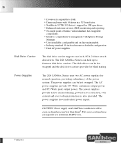
...; Intuitive, comprehensive management with Spheras Storage Manager. • User installable, configurable and on-line maintainable. • Industry-standard 19-inch rackmount or deskside configuration. • Dual AC power supplies. The power supplies have conductors with a cross-sectional area not less than 4mm2. Features The disk drives can be hot swapped and the disk drive carriers provide for blind mating. The power supplies provide active current sharing, power factor correction, over...
...; Intuitive, comprehensive management with Spheras Storage Manager. • User installable, configurable and on-line maintainable. • Industry-standard 19-inch rackmount or deskside configuration. • Dual AC power supplies. The power supplies have conductors with a cross-sectional area not less than 4mm2. Features The disk drives can be hot swapped and the disk drive carriers provide for blind mating. The power supplies provide active current sharing, power factor correction, over...

Installation Guide
Page 23
... host fibre channel and two device fibre channel interfaces. The controller enables multiple hosts to access an array of disk drives, which can be configured as one or more virtual storage devices (logical units). The top connector is the FC Loop Input port and the bottom connector is for FC Loop Expansion. 23 I/O Expansion Module- Optical/Optical This 2Gb FC expansion module has two SFF LC optical...
... host fibre channel and two device fibre channel interfaces. The controller enables multiple hosts to access an array of disk drives, which can be configured as one or more virtual storage devices (logical units). The top connector is the FC Loop Input port and the bottom connector is for FC Loop Expansion. 23 I/O Expansion Module- Optical/Optical This 2Gb FC expansion module has two SFF LC optical...

Installation Guide
Page 28
... statements refer to a power source which carries a fuse or circuit breaker that is greater than the rating of the components, ensure that anti-static precautions are removed the resulting hole must be blocked, by installing a component blank or replacing the component. CAUTION: This device should be connected to Appendix B. The minimum requirement is intended only for installation in a restricted access location...
... statements refer to a power source which carries a fuse or circuit breaker that is greater than the rating of the components, ensure that anti-static precautions are removed the resulting hole must be blocked, by installing a component blank or replacing the component. CAUTION: This device should be connected to Appendix B. The minimum requirement is intended only for installation in a restricted access location...

Installation Guide
Page 32
... be operated with fibre channel loop speeds of current at start-up time as they do during steady state operation. 32 Electrical Considerations When installing the 2Gb SANbloc Series the following procedures must be added to arrive at JP2. 4 Replace the LS module. This includes cabling, power distribution units, filters and any other devices through the use of the enclosure. 2 On the...
... be operated with fibre channel loop speeds of current at start-up time as they do during steady state operation. 32 Electrical Considerations When installing the 2Gb SANbloc Series the following procedures must be added to arrive at JP2. 4 Replace the LS module. This includes cabling, power distribution units, filters and any other devices through the use of the enclosure. 2 On the...
Installation Guide
Page 33
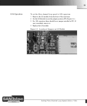
Figure 2-1 Location of the enclosure. 2 On the LS Module locate the jumper position JP2 (Figure 2-1). 3 For 1Gb operation there should be no jumper installed at JP2. If one is installed, remove it. 4 Replace the LS module. 33 1Gb Operation To set the fibre channel loop speed to 1Gb operation: 1 Remove the LS module from the front of Jumpers on LS Module Setting Fibre Channel Loop Speed (2Gb or 1Gb)
Figure 2-1 Location of the enclosure. 2 On the LS Module locate the jumper position JP2 (Figure 2-1). 3 For 1Gb operation there should be no jumper installed at JP2. If one is installed, remove it. 4 Replace the LS module. 33 1Gb Operation To set the fibre channel loop speed to 1Gb operation: 1 Remove the LS module from the front of Jumpers on LS Module Setting Fibre Channel Loop Speed (2Gb or 1Gb)

Installation Guide
Page 34
... LS module allows for split FC Loop operation, with two dual fibre channel loops of the enclosure. 2 On the LS Module locate the jumper position JP3 (Figure 2-1). 3 To operate in split loop mode can not be applied to both LS modules. In this procedure: 1 Remove the LS module from right hand side of rackmount systems). The expansion port (I / O Slot A) will form a second loop using the...
... LS module allows for split FC Loop operation, with two dual fibre channel loops of the enclosure. 2 On the LS Module locate the jumper position JP3 (Figure 2-1). 3 To operate in split loop mode can not be applied to both LS modules. In this procedure: 1 Remove the LS module from right hand side of rackmount systems). The expansion port (I / O Slot A) will form a second loop using the...

Installation Guide
Page 41
... with support for connecting a dual FC Loop configuration to your host computer, and how to daisy chain enclosures) • Quad Loop (single enclosure with 4 FCAL loops) Note: The following examples show the Copper/Copper I/O Module option for all I/O Module options. 41 JBOD Configurations There are identical for illustration purposes. A hub, switch or two hosts with HBA may also be two LS modules installed in...
... with support for connecting a dual FC Loop configuration to your host computer, and how to daisy chain enclosures) • Quad Loop (single enclosure with 4 FCAL loops) Note: The following examples show the Copper/Copper I/O Module option for all I/O Module options. 41 JBOD Configurations There are identical for illustration purposes. A hub, switch or two hosts with HBA may also be two LS modules installed in...
Installation Guide
Page 47
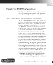
The failed controller can be removed and replaced while the system is online. The controller provides continuous access to data in which can then be configured as one in the event of a controller failure. The new controller resumes processing array operations in the event of a disk drive failure. This dual-active controller system is maintained with the disk drives. Some general information about...
The failed controller can be removed and replaced while the system is online. The controller provides continuous access to data in which can then be configured as one in the event of a controller failure. The new controller resumes processing array operations in the event of a disk drive failure. This dual-active controller system is maintained with the disk drives. Some general information about...
Installation Guide
Page 50
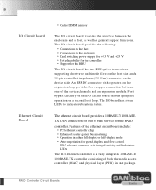
... HSSDC connector with integral activity and link status LEDs The PCI ethernet controller is a fully integrated 10BASE-T/ 100BASE-TX controller consisting of both the media access controller (MAC) and physical layer (PHY) in either full duplex or half-duplex mode • Auto-negotiation for speed, duplex, and flow control • RJ45 ethernet connector with repeaters on the expansion loop provides for a copper connection between the enclosure...
... HSSDC connector with integral activity and link status LEDs The PCI ethernet controller is a fully integrated 10BASE-T/ 100BASE-TX controller consisting of both the media access controller (MAC) and physical layer (PHY) in either full duplex or half-duplex mode • Auto-negotiation for speed, duplex, and flow control • RJ45 ethernet connector with repeaters on the expansion loop provides for a copper connection between the enclosure...

Installation Guide
Page 58
To next enclosure CAUTION: When daisy chaining enclosures, you must ensure that each enclosure has a unique Enclosure ID. 58 I/O Module Figure 4-6 Daisy Chaining Single Controller Enclosure RAID Controller HBA 1 1 1 HBA 2 2 2 1 2 3 4 5 6 7 0 0 I I Link Cable Connect this cable for dual loop operation 1 2 Link Cable 1 2 0 0 I I To next enclosure Total of 8 enclosures may be daisy chained together. Configurations
To next enclosure CAUTION: When daisy chaining enclosures, you must ensure that each enclosure has a unique Enclosure ID. 58 I/O Module Figure 4-6 Daisy Chaining Single Controller Enclosure RAID Controller HBA 1 1 1 HBA 2 2 2 1 2 3 4 5 6 7 0 0 I I Link Cable Connect this cable for dual loop operation 1 2 Link Cable 1 2 0 0 I I To next enclosure Total of 8 enclosures may be daisy chained together. Configurations

Installation Guide
Page 65
... front mounted LS module is the main monitoring device of the monitoring LEDs and how to provide active/passive fail-over the Enclosure Services Interface (ESI) port of the fourteen disk drives installed in the enclosure. The LS Module also provides loop resiliency for the Fibre Channel loop (in the following sections. The location of the 2Gb SANbloc Series. All these monitoring devices are discussed in...
... front mounted LS module is the main monitoring device of the monitoring LEDs and how to provide active/passive fail-over the Enclosure Services Interface (ESI) port of the fourteen disk drives installed in the enclosure. The LS Module also provides loop resiliency for the Fibre Channel loop (in the following sections. The location of the 2Gb SANbloc Series. All these monitoring devices are discussed in...

Installation Guide
Page 68
... FC Loop A open . OFF indicates FC Loop B open ON indicates FC Loop B closed . ON indicates the FC loop is operating at 2Gb/Sec speed. LS Module 68 Table 5-1 Enclosure LED Descriptions LED 0 LED 1 LED 2 LED 3 LED 4 LED 5 Description Color Indication Power On Shelf Fault Green Amber FC Loop A FC Loop B LS Fault Green Green Amber 2Gb Operation Green Normally ON, indicates power is a 1GB LS module in the enclosure. ON indicates FC Loop A closed . Flashing...
... FC Loop A open . OFF indicates FC Loop B open ON indicates FC Loop B closed . ON indicates the FC loop is operating at 2Gb/Sec speed. LS Module 68 Table 5-1 Enclosure LED Descriptions LED 0 LED 1 LED 2 LED 3 LED 4 LED 5 Description Color Indication Power On Shelf Fault Green Amber FC Loop A FC Loop B LS Fault Green Green Amber 2Gb Operation Green Normally ON, indicates power is a 1GB LS module in the enclosure. ON indicates FC Loop A closed . Flashing...

Installation Guide
Page 95
... modules, removable from the rear. • Two loop resiliency and SES modules (LS), removable from the front. • Up to 14 disk drives, removable from the front. • Two independent AC power inlets. Host Interface 95 Appendix B: Technical Specifications Host Interface • One or two Fibre Channel interfaces, 200MB\s each , 400MB\s total. Disk Drive Interface • Dual independent Fibre Channel interfaces, 200MB\s each , 400 MB\s total. • External hub and switch support...
... modules, removable from the rear. • Two loop resiliency and SES modules (LS), removable from the front. • Up to 14 disk drives, removable from the front. • Two independent AC power inlets. Host Interface 95 Appendix B: Technical Specifications Host Interface • One or two Fibre Channel interfaces, 200MB\s each , 400MB\s total. Disk Drive Interface • Dual independent Fibre Channel interfaces, 200MB\s each , 400 MB\s total. • External hub and switch support...

Installation Guide
Page 96
audible alarm; Spheras Storage Management software. LEDs; 96 Physical Dimensions Deskside Enclosure Height: 20 inches (50.8cm) Width: 9 inches (22.9cm) Depth: 20 inches (50.8cm) Weight: 60 lbs (29.5kg) maximum Rack Enclosure Height: 5.22 inches (13.3cm) Width: 17.5 inches (44.5cm) Depth: 20 inches (50.8cm) Weight: 60 lbs (29.5kg) maximum Warranty Three (3) years (5 years disk drive warranty) Monitoring Temperature, advanced cooling modules, power supplies, disk drives, loop resiliency modules, I/O modules Failure Notification In-band reporting SES; Physical Dimensions
audible alarm; Spheras Storage Management software. LEDs; 96 Physical Dimensions Deskside Enclosure Height: 20 inches (50.8cm) Width: 9 inches (22.9cm) Depth: 20 inches (50.8cm) Weight: 60 lbs (29.5kg) maximum Rack Enclosure Height: 5.22 inches (13.3cm) Width: 17.5 inches (44.5cm) Depth: 20 inches (50.8cm) Weight: 60 lbs (29.5kg) maximum Warranty Three (3) years (5 years disk drive warranty) Monitoring Temperature, advanced cooling modules, power supplies, disk drives, loop resiliency modules, I/O modules Failure Notification In-band reporting SES; Physical Dimensions

Installation Guide
Page 110
110 loop resiliency and ses module, 65 ls module, 79 M modulo 8 63 monitoring, system, 65, 96 N notification, 96 O operating temperature, 30 P port bypass circuits, 65 power consumption 32 power output 20 power rating, 32 power source 62 power supplies, 20, 81, 97 power supplies, leds, 71 R rack mounting, 30 raid, 45 redundancy, 95 regulatory agency, 99 S safety statements, 16, 28 safety statements, translations, 28, 85 shock...
110 loop resiliency and ses module, 65 ls module, 79 M modulo 8 63 monitoring, system, 65, 96 N notification, 96 O operating temperature, 30 P port bypass circuits, 65 power consumption 32 power output 20 power rating, 32 power source 62 power supplies, 20, 81, 97 power supplies, leds, 71 R rack mounting, 30 raid, 45 redundancy, 95 regulatory agency, 99 S safety statements, 16, 28 safety statements, translations, 28, 85 shock...