
Service Guide
Page 4
... any defect in this guide is subject to the contents hereof and specifically disclaims any particular purpose. iv Should the programs prove defective following their respective holders. Intel is a registered trademark of merchantability or fitness for any warranties of Acer Corporation. Disclaimer The information in this manual is sold or licensed "as...
... any defect in this guide is subject to the contents hereof and specifically disclaims any particular purpose. iv Should the programs prove defective following their respective holders. Intel is a registered trademark of merchantability or fitness for any warranties of Acer Corporation. Disclaimer The information in this manual is sold or licensed "as...

Service Guide
Page 5
v Conventions The following conventions are used in this manual: SCREEN MESSAGES NOTE WARNING CAUTION IMPORTANT Denotes actual messages that might result from doing or not doing specific actions. Alerts you to do specific actions relevant to the current topic. Gives precautionary measures to avoid possible hardware or software problems. Reminds you to any physical risk or system damage that appear on screen. Gives additional information related to the accomplishment of procedures.
v Conventions The following conventions are used in this manual: SCREEN MESSAGES NOTE WARNING CAUTION IMPORTANT Denotes actual messages that might result from doing or not doing specific actions. Alerts you to do specific actions relevant to the current topic. Gives precautionary measures to avoid possible hardware or software problems. Reminds you to any physical risk or system damage that appear on screen. Gives additional information related to the accomplishment of procedures.

Service Guide
Page 7
Table of Contents System Tour Features Block Diagram System Components Front Panel Rear Panel Hardware Specifications and Configurations Power Management Function(ACPI support function) 1 1 5 6 6 7 8 11 System Utilities CMOS Setup Utility Entering CMOS setup Navigating Through the Setup Utility Setup Utility Menus ...
Table of Contents System Tour Features Block Diagram System Components Front Panel Rear Panel Hardware Specifications and Configurations Power Management Function(ACPI support function) 1 1 5 6 6 7 8 11 System Utilities CMOS Setup Utility Entering CMOS setup Navigating Through the Setup Utility Setup Utility Menus ...

Service Guide
Page 12
...by default). Demand for worldwide. Minimum 1 small 4-pin power connector included. Four 2*5 pin Intel FPIO specification USB pin connectors (follow Intel FPIO standard Specification). One 4 pin CPU Fan connector. One on board buzzer. One 2pin Intrusion Alarm connector. One ...2*4 pin internal speaker header. Braidwood slot (reserved). One 2*7 pin front panel IO header. Power supply 300W/ in stable mode (Acer/GTW Assign System Power Unit). Compliant with Energy Star 5.0(Veriton...
...by default). Demand for worldwide. Minimum 1 small 4-pin power connector included. Four 2*5 pin Intel FPIO specification USB pin connectors (follow Intel FPIO standard Specification). One 4 pin CPU Fan connector. One on board buzzer. One 2pin Intrusion Alarm connector. One ...2*4 pin internal speaker header. Braidwood slot (reserved). One 2*7 pin front panel IO header. Power supply 300W/ in stable mode (Acer/GTW Assign System Power Unit). Compliant with Energy Star 5.0(Veriton...

Service Guide
Page 16
... in BIOS Setup is set to Enabled.) BIOS Item BIOS code programmer BIOS version BIOS ROM type BIOS ROM size Support protocol Device Boot Support Specification AMI Kernel skin P01-A0 SPI ROM 64Mb(Piketon vPro) SMBIOS2.6.1 1st priority: SATA HDD 2nd priority: CD-ROM 3rd priority: Removable Device 4rd ...is booting to enter BIOS Setup Utility. Main Board Major Chips Item North Bridge South Bridge VGA controller Audio controller LAN controller USB controller SATA 8 Specification Intel Q57 Intel Q57 Intel Q57 Intel Q57+ALC662-VC Intel Q57+Intel Hanksville-D 82578DM Intel Q57 Intel Q57 Chapter 1
... in BIOS Setup is set to Enabled.) BIOS Item BIOS code programmer BIOS version BIOS ROM type BIOS ROM size Support protocol Device Boot Support Specification AMI Kernel skin P01-A0 SPI ROM 64Mb(Piketon vPro) SMBIOS2.6.1 1st priority: SATA HDD 2nd priority: CD-ROM 3rd priority: Removable Device 4rd ...is booting to enter BIOS Setup Utility. Main Board Major Chips Item North Bridge South Bridge VGA controller Audio controller LAN controller USB controller SATA 8 Specification Intel Q57 Intel Q57 Intel Q57 Intel Q57+ALC662-VC Intel Q57+Intel Hanksville-D 82578DM Intel Q57 Intel Q57 Chapter 1
Service Guide
Page 17
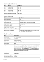
...Memory Item Memory slot number Support Memory size per socket Support memory type Support memory interface Support memory voltage Support to parity check feature Specification 4 slot 1GB/2GB/4GB DDR3 1333/1066 Un-buffered Non-ECC/ DIMM DDR3 connector 1.5V Yes Support to error correction code ...and game experience for PC users. Audio Interface Item Audio controller Audio controller type Audio channel Audio function control Mono or stereo Compatibility Specification Intel Q57+ALC662-VC ALC662-VC codec 5.1(Rear 3 jack) Enable/Disable by BIOS setup Stereo The ALC662-VC series support host ...
...Memory Item Memory slot number Support Memory size per socket Support memory type Support memory interface Support memory voltage Support to parity check feature Specification 4 slot 1GB/2GB/4GB DDR3 1333/1066 Un-buffered Non-ECC/ DIMM DDR3 connector 1.5V Yes Support to error correction code ...and game experience for PC users. Audio Interface Item Audio controller Audio controller type Audio channel Audio function control Mono or stereo Compatibility Specification Intel Q57+ALC662-VC ALC662-VC codec 5.1(Rear 3 jack) Enable/Disable by BIOS setup Stereo The ALC662-VC series support host ...

Service Guide
Page 18
...Interface Item SATA controller SATA controller resident bus Number of SATA channel Support bootable CD-ROM Specification Intel Q57 PCI bus SATA X 6 YES USB Port Item Universal HCI USB Class USB Connectors Quantity Specification USB 2.0/1.1 Support legacy keyboard for legacy mode 6 back rear ports On-board: 4 ... axis in all 3 axes. 15% to 80% RH 10% to 90% RH +5°C ~ +35°C -20 ~ +60°C (Storage package) Specification Power Management Devices Power Button USB Keyboard/Mouse PME RCT WOR • • S1 V V Disabled Disabled Disabled S3 V V Disabled Disabled Disabled S4 V N/A ...
...Interface Item SATA controller SATA controller resident bus Number of SATA channel Support bootable CD-ROM Specification Intel Q57 PCI bus SATA X 6 YES USB Port Item Universal HCI USB Class USB Connectors Quantity Specification USB 2.0/1.1 Support legacy keyboard for legacy mode 6 back rear ports On-board: 4 ... axis in all 3 axes. 15% to 80% RH 10% to 90% RH +5°C ~ +35°C -20 ~ +60°C (Storage package) Specification Power Management Devices Power Button USB Keyboard/Mouse PME RCT WOR • • S1 V V Disabled Disabled Disabled S3 V V Disabled Disabled Disabled S4 V N/A ...
Service Guide
Page 19
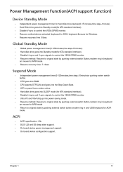
... monitor. Disable H-sync and V-sync signals to control the VESA DPMS monitor. Hard disk drive goes into Standby mode(for ACPI mode. • ACPI ACPI specification 1.0b S0,S1,S2 and S5 sleep state support. Power Management Function(ACPI support function) Device Standby Mode Independent power management timer for ATA standard...
... monitor. Disable H-sync and V-sync signals to control the VESA DPMS monitor. Hard disk drive goes into Standby mode(for ACPI mode. • ACPI ACPI specification 1.0b S0,S1,S2 and S5 sleep state support. Power Management Function(ACPI support function) Device Standby Mode Independent power management timer for ATA standard...

Service Guide
Page 62
... POST. Bootblock code is copied from add-in cards that show the value of the screen during the preboot process. Both key sequence and OEM specific method is checked to checkpoint E0. Main BIOS checksum is done including RTC and keyboard controller. Leaves all checkpoints generated by the BIOS requires acheckpoint...
... POST. Bootblock code is copied from add-in cards that show the value of the screen during the preboot process. Both key sequence and OEM specific method is checked to checkpoint E0. Main BIOS checksum is done including RTC and keyboard controller. Leaves all checkpoints generated by the BIOS requires acheckpoint...

Service Guide
Page 64
... file size. Some interrupt vectors are initialized. Recovery file not found flash part size. Disable L1 cache. Make flash write enabled through chipset and OEM specific method. The recovery file size does not equal the found . Erase the flash part Program the flash part. DMA controller is initialized. 8259 interrupt controller...
... file size. Some interrupt vectors are initialized. Recovery file not found flash part size. Disable L1 cache. Make flash write enabled through chipset and OEM specific method. The recovery file size does not equal the found . Erase the flash part Program the flash part. DMA controller is initialized. 8259 interrupt controller...