
Veriton 3600G/5600G/7600G Service Guide
Page 11
...(865PE chipset) T 8X AGP expansion slots T DDR-SDRAM 400/333/266, 4 DIMM slots, expandable to 120GB T Supports USB 2.0 high-performance peripherals T Plug-and-Play (PnP) feature T Software shutdown for Veriton 3600G, 5600G and 7600G) 2 Veriton 3600(G/D)/5600(G/D)/7600(G/D) However, you can ... T High-capacity, Enhanced-IDE hard disc, up function Expansion T 3 PCI slots + 4 DIMM slots+ 1 AGP slot ( AGP slot for Windows XP Prefessional/ Home edition Multimedia T 128-bit graphics accelerator installed in the AGP Pro card slot T Cathode-ray tube (CRT) support T Liquid crystal display (LCD) ...
...(865PE chipset) T 8X AGP expansion slots T DDR-SDRAM 400/333/266, 4 DIMM slots, expandable to 120GB T Supports USB 2.0 high-performance peripherals T Plug-and-Play (PnP) feature T Software shutdown for Veriton 3600G, 5600G and 7600G) 2 Veriton 3600(G/D)/5600(G/D)/7600(G/D) However, you can ... T High-capacity, Enhanced-IDE hard disc, up function Expansion T 3 PCI slots + 4 DIMM slots+ 1 AGP slot ( AGP slot for Windows XP Prefessional/ Home edition Multimedia T 128-bit graphics accelerator installed in the AGP Pro card slot T Cathode-ray tube (CRT) support T Liquid crystal display (LCD) ...

Veriton 3600G/5600G/7600G Service Guide
Page 32
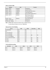
... Specification BIOS code programmer Award BIOS version V6.0 BIOS ROM type Intel FWH SST 49LF004-33-4C-NH BIOS ROM size 4MB Support protocol PCI 2.1, APM1.2, DMI 2.00.1, E-IDE, ACPI 1.0, ESCD 1.03, ANSI ATA 3.0, PnP 1a, Bootable CD-ROM 1.0, ATAPI Boot from ... FLASH utility (AWDFLASH.EXE). The items on the Advanced Options menu are: Memory/Cache Options PnP/PCI Options Chips Options Chapter 1 23 Hardware Specifications and Configurations Processor Type Item Slot Speed Minimum operating speed Voltage Specification Intel® Pentium 4 Northwood FSB400/533/800MHz; Intel® ...
... Specification BIOS code programmer Award BIOS version V6.0 BIOS ROM type Intel FWH SST 49LF004-33-4C-NH BIOS ROM size 4MB Support protocol PCI 2.1, APM1.2, DMI 2.00.1, E-IDE, ACPI 1.0, ESCD 1.03, ANSI ATA 3.0, PnP 1a, Bootable CD-ROM 1.0, ATAPI Boot from ... FLASH utility (AWDFLASH.EXE). The items on the Advanced Options menu are: Memory/Cache Options PnP/PCI Options Chips Options Chapter 1 23 Hardware Specifications and Configurations Processor Type Item Slot Speed Minimum operating speed Voltage Specification Intel® Pentium 4 Northwood FSB400/533/800MHz; Intel® ...
Veriton 3600G/5600G/7600G Service Guide
Page 38
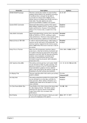
...Device Intel 845G MCH P2P (Func.0) ICH4 (LPC) (Func.1) ICH4 (IDE) (Func.2) ICH4(USB) (Func.3) ICH4 (SMBUS) (Func.5) ICH4 (AC97 Audio) PCI Slot 1 PCI Slot 2 PCI Slot 3 AD# AD11 AD30 AD31 AD31 AD31 AD31 AD31 AD16 AD17 AD21 IDSEL 00h 13h 14h 14h 14h 14h 14h 05h 06h 07h Route Reg. The... Main Memory Maximum size are 768M Bytes. Mask 68h FFh 61h FFh 60h FFh 61h FFh 62h FFh PCI Slot IRQ Routing Map PCI INTX# PCI 1 PCI 2 PCI 3 INTA Route 1 Route 4 Route 3 INTB Route 2 Route 1 Route 4 INTC Route 3 Route 2 Route 1 INTD Route 4 Route 3 Route 2 Chapter 1 29 ...
...Device Intel 845G MCH P2P (Func.0) ICH4 (LPC) (Func.1) ICH4 (IDE) (Func.2) ICH4(USB) (Func.3) ICH4 (SMBUS) (Func.5) ICH4 (AC97 Audio) PCI Slot 1 PCI Slot 2 PCI Slot 3 AD# AD11 AD30 AD31 AD31 AD31 AD31 AD31 AD16 AD17 AD21 IDSEL 00h 13h 14h 14h 14h 14h 14h 05h 06h 07h Route Reg. The... Main Memory Maximum size are 768M Bytes. Mask 68h FFh 61h FFh 60h FFh 61h FFh 62h FFh PCI Slot IRQ Routing Map PCI INTX# PCI 1 PCI 2 PCI 3 INTA Route 1 Route 4 Route 3 INTB Route 2 Route 1 Route 4 INTC Route 3 Route 2 Route 1 INTD Route 4 Route 3 Route 2 Chapter 1 29 ...
Veriton 3600G/5600G/7600G Service Guide
Page 53
... is the video memory that hit the aperture range are forwarded to the AGP without any program writes to use as the display(s) of the PCI memory address range dedicated to graphics memory address space. However, if any program writes to C7FFFh, resulting in better system performance. Disabled Enabled When the... data for video display (frame). When setting to Enabled, up to 128MB system RAM will be reserved for ISA peripherals. This field is your primary PCI Slot graphics adapter.
... is the video memory that hit the aperture range are forwarded to the AGP without any program writes to use as the display(s) of the PCI memory address range dedicated to graphics memory address space. However, if any program writes to C7FFFh, resulting in better system performance. Disabled Enabled When the... data for video display (frame). When setting to Enabled, up to 128MB system RAM will be reserved for ISA peripherals. This field is your primary PCI Slot graphics adapter.

Veriton 3600G/5600G/7600G Service Guide
Page 73
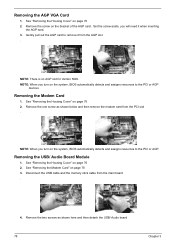
See "Removing the Housing Cover" on page 63 2. NOTE: There is no AGP VGA slot for Veriton 3500. Remove the screw as shown here. 3. Removing the AGP VGA Card 1. Remove the four screws as shown here and then remove the AGP VGA card from the front panel gently in the way as shown here. Detach the front bezel from the slot. See "Removing the Housing Cover" on page 63 2. Removing the Front Panel 1. NOTE: When you turn on the system, BIOS automatically detects and assigns resources to the PCI or AGP devices. 64 Chapter 3
See "Removing the Housing Cover" on page 63 2. NOTE: There is no AGP VGA slot for Veriton 3500. Remove the screw as shown here. 3. Removing the AGP VGA Card 1. Remove the four screws as shown here and then remove the AGP VGA card from the front panel gently in the way as shown here. Detach the front bezel from the slot. See "Removing the Housing Cover" on page 63 2. Removing the Front Panel 1. NOTE: When you turn on the system, BIOS automatically detects and assigns resources to the PCI or AGP devices. 64 Chapter 3
Veriton 3600G/5600G/7600G Service Guide
Page 87
NOTE: There is no AGP slot for Veriton 5600. Removing the Modem Card 1. Gently pull out the AGP card to remove it when inserting the AGP card. 3. See "Removing the Housing Cover" on page 76 2. Set the screw aside, you will need it from the AGP slot . See "Removing the Housing Cover"...remove the modem card from the main board . 4. Removing the USB/ Audio Board Module 1. Disconnect the USB cable and the memory stick cable from the PCI slot . See "Removing the Modem Card" on page 76 2. See "Removing the Housing Cover" on page 78 3. Remove the one screw as shown here ...
NOTE: There is no AGP slot for Veriton 5600. Removing the Modem Card 1. Gently pull out the AGP card to remove it when inserting the AGP card. 3. See "Removing the Housing Cover" on page 76 2. Set the screw aside, you will need it from the AGP slot . See "Removing the Housing Cover"...remove the modem card from the main board . 4. Removing the USB/ Audio Board Module 1. Disconnect the USB cable and the memory stick cable from the PCI slot . See "Removing the Modem Card" on page 76 2. See "Removing the Housing Cover" on page 78 3. Remove the one screw as shown here ...

Veriton 3600G/5600G/7600G Service Guide
Page 99
NOTE: There is no AGP VGA slot for Veriton 7500. Set the screw aside, you will need it when reinserting the modem card . NOTE: When you will need it when reinserting the AGP card. 3. Gently pull out the modem card to remove it from the PCI slot. Set the screw aside, you turn ...on the system, BIOS automatically detects and assigns resources to remove it from the AGP slot. . 4. See "Removing the Housing" on the bracket of the modem card. Gently ...
NOTE: There is no AGP VGA slot for Veriton 7500. Set the screw aside, you will need it when reinserting the modem card . NOTE: When you will need it when reinserting the AGP card. 3. Gently pull out the modem card to remove it from the PCI slot. Set the screw aside, you turn ...on the system, BIOS automatically detects and assigns resources to remove it from the AGP slot. . 4. See "Removing the Housing" on the bracket of the modem card. Gently ...

Veriton 3600G/5600G/7600G Service Guide
Page 114
.... a value of RTC value: e.g. Prepare BIOS resource map for Pentium class CPU. 3. Initialize the APIC for PCI & PnP use default value instead. 3. Program early chipset according to empty PCI & DIMM slots. 5. Early PCI initialization -Enumerate PCI bus number -Assign memory & I /O chips. Reserved Reserved Reserved 1. Initialize multi-language 2. Reserved Test 8259 interrupt .... Measure CPU speed. 5. Invoke video BIOS. Put information on screen display, including Award title, CPU type, CPU speed... Reserved Reserved 105 Veriton 3600(D/G)/5600(D/G)/7600(D/G)
.... a value of RTC value: e.g. Prepare BIOS resource map for Pentium class CPU. 3. Initialize the APIC for PCI & PnP use default value instead. 3. Program early chipset according to empty PCI & DIMM slots. 5. Early PCI initialization -Enumerate PCI bus number -Assign memory & I /O chips. Reserved Reserved Reserved 1. Initialize multi-language 2. Reserved Test 8259 interrupt .... Measure CPU speed. 5. Invoke video BIOS. Put information on screen display, including Award title, CPU type, CPU speed... Reserved Reserved 105 Veriton 3600(D/G)/5600(D/G)/7600(D/G)

Veriton 3600G/5600G/7600G Service Guide
Page 122
...used, reinsert the modem card to receive messages and/or fax. 1. Remove all non-factory-installed cards. 2. Monitor 3. Main board 113 Veriton 3600(D/G)/5600(D/G)/7600(D/G) Error Symptom Audio software program invokes but no sound comes from modem cannot be produced, but has no sound output. ...from modem adapter card to Enabled. 2. Ensure the modem voice-in BIOS Setup or Power Management is configured correctly for your modem and set to PCI slot firmly or replace the modem card. 3. Main board 1. Monitor signal connection/cable 2. Main board 1. Modem 1. In Win 98, ensure the ...
...used, reinsert the modem card to receive messages and/or fax. 1. Remove all non-factory-installed cards. 2. Monitor 3. Main board 113 Veriton 3600(D/G)/5600(D/G)/7600(D/G) Error Symptom Audio software program invokes but no sound comes from modem cannot be produced, but has no sound output. ...from modem adapter card to Enabled. 2. Ensure the modem voice-in BIOS Setup or Power Management is configured correctly for your modem and set to PCI slot firmly or replace the modem card. 3. Main board 1. Monitor signal connection/cable 2. Main board 1. Modem 1. In Win 98, ensure the ...

Veriton 3600G/5600G/7600G Service Guide
Page 154
... 99 MPU-401 25 N Network port 12, 14, 18 O Online Support Information 142 Overview 1, 133 P Parallel Port 28 Parallel/printer port 12, 14, 18 PCI INTx# 29 PCI Slot IRQ 29 ports left panel 12, 14, 18 POST 103 Power button 10, 17 Power LED 10, 17 Power-On Self-Test (POST) 103... Specifications 1, 133 design 3 Features 2 T Temperature 31 Test Compatible Components 134 Troubleshooting 102 U UART 28 Undetermined Problems 115 USB Port 28 USB ports 13, 15, 19 V Veriton 133 Vibration 31 Voltage 32 Voltage selector switch 13, 15, 19 W Index
... 99 MPU-401 25 N Network port 12, 14, 18 O Online Support Information 142 Overview 1, 133 P Parallel Port 28 Parallel/printer port 12, 14, 18 PCI INTx# 29 PCI Slot IRQ 29 ports left panel 12, 14, 18 POST 103 Power button 10, 17 Power LED 10, 17 Power-On Self-Test (POST) 103... Specifications 1, 133 design 3 Features 2 T Temperature 31 Test Compatible Components 134 Troubleshooting 102 U UART 28 Undetermined Problems 115 USB Port 28 USB ports 13, 15, 19 V Veriton 133 Vibration 31 Voltage 32 Voltage selector switch 13, 15, 19 W Index

Veriton 5600G
Page 72
... connector (12V power) One Touch Recovery button connector Parallel/Printer port PCI slots 1 to 3 Serial HDD connectors Serial port Northbridge Southbridge USB ports Front USB 2.0 connector or Unused Front USB 2.0 connector or Unused USB ports Monitor port (VT5600G only) Note: For the location of the AGP slot on the Veriton 5600G mainboard, see page 64.
... connector (12V power) One Touch Recovery button connector Parallel/Printer port PCI slots 1 to 3 Serial HDD connectors Serial port Northbridge Southbridge USB ports Front USB 2.0 connector or Unused Front USB 2.0 connector or Unused USB ports Monitor port (VT5600G only) Note: For the location of the AGP slot on the Veriton 5600G mainboard, see page 64.

Veriton 5600G
Page 79
73 8 Reinstall the metal bracket frame to the computer. Save the screw. Installing an expansion card To install an expansion card: 1 Remove the computer cover. 2 Locate an empty PCI slot on the mainboard. 3 Remove the screw that holds the bracket to the housing. 9 Replace the computer cover.
73 8 Reinstall the metal bracket frame to the computer. Save the screw. Installing an expansion card To install an expansion card: 1 Remove the computer cover. 2 Locate an empty PCI slot on the mainboard. 3 Remove the screw that holds the bracket to the housing. 9 Replace the computer cover.


