User Manual
Page 11
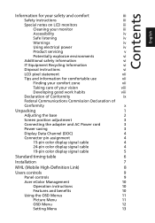
... 3 Power saving 3 Display Data Channel (DDC) 4 Connector pin assignment 4 15-pin color display signal cable 4 24-pin color display signal cable 4 19-pin color display signal cable 5 Standard timing table 6 Installation 7 MHL (Mobile High-Definition Link) 8 Users controls 9 Panel controls 9 Acer eColor Management 10 Operation instructions 10 Features and benefits 10 Using the OSD Menus...
... 3 Power saving 3 Display Data Channel (DDC) 4 Connector pin assignment 4 15-pin color display signal cable 4 24-pin color display signal cable 4 19-pin color display signal cable 5 Standard timing table 6 Installation 7 MHL (Mobile High-Definition Link) 8 Users controls 9 Panel controls 9 Acer eColor Management 10 Operation instructions 10 Features and benefits 10 Using the OSD Menus...

User Manual
Page 13
English Unpacking Please check that the following items are present when you unpack the box, and save the packing materials in case you need to ship or transport the monitor in the future. LCD monitor User guide Quick start guide VGA cable AC Adapter AC Power cord HDMI cable (Optional) DVI cable (Optional) Audio cable (Optional) MHL Cable (Optional) 1
English Unpacking Please check that the following items are present when you unpack the box, and save the packing materials in case you need to ship or transport the monitor in the future. LCD monitor User guide Quick start guide VGA cable AC Adapter AC Power cord HDMI cable (Optional) DVI cable (Optional) Audio cable (Optional) MHL Cable (Optional) 1
User Manual
Page 16
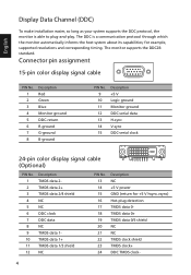
...TMDS data 0/5 shield NC NC TMDS clock shield TMDS clock+ DDC TMDS clock- 4 Connector pin assignment 15-pin color display signal cable 1 5 6 10 11 15 PIN No. 1 2 3 4 5 6 7 8 Description Red Green Blue Monitor ground DDC-...14 15 Description +5 V Logic ground Monitor ground DDC-serial data H-sync V-sync DDC-serial clock 24-pin color display signal cable (Optional) PIN No. 1 2 3 4 5 6 7 8 9 10 11 12 Description TMDS data 2TMDS data 2+ ...19 20 21 22 23 24 Description NC +5 V power GND (return for example, supported resolutions and corresponding timing. The DDC is able to plug-and-play...
...TMDS data 0/5 shield NC NC TMDS clock shield TMDS clock+ DDC TMDS clock- 4 Connector pin assignment 15-pin color display signal cable 1 5 6 10 11 15 PIN No. 1 2 3 4 5 6 7 8 Description Red Green Blue Monitor ground DDC-...14 15 Description +5 V Logic ground Monitor ground DDC-serial data H-sync V-sync DDC-serial clock 24-pin color display signal cable (Optional) PIN No. 1 2 3 4 5 6 7 8 9 10 11 12 Description TMDS data 2TMDS data 2+ ...19 20 21 22 23 24 Description NC +5 V power GND (return for example, supported resolutions and corresponding timing. The DDC is able to plug-and-play...
User Manual
Page 17
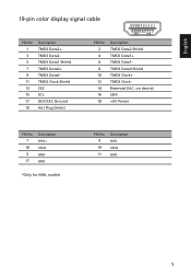
on device) SDA +5V Power PIN No. 7 18 5 17 Description MHL+ VBUS GND GND *Only for MHL models PIN No. 9 19 11 Description MHL CBUS GND 5 English 19-pin color display signal cable 19 171513 11 9 7 5 3 1 18161412 10 8 6 4 2 PIN No. 1 3 5 7 9 11 13 15 17 19 Description TMDS Data2+ TMDS Data2TMDS Data1 Shield TMDS Data0+ TMDS Data0TMDS Clock Shield CEC SCL DDC/CEC Ground Hot Plug Detect PIN No. 2 4 6 8 10 12 14 16 18 Description TMDS Data2 Shield TMDS Data1+ TMDS Data1TMDS Data0 Shield TMDS Clock+ TMDS ClockReserved (N.C.
on device) SDA +5V Power PIN No. 7 18 5 17 Description MHL+ VBUS GND GND *Only for MHL models PIN No. 9 19 11 Description MHL CBUS GND 5 English 19-pin color display signal cable 19 171513 11 9 7 5 3 1 18161412 10 8 6 4 2 PIN No. 1 3 5 7 9 11 13 15 17 19 Description TMDS Data2+ TMDS Data2TMDS Data1 Shield TMDS Data0+ TMDS Data0TMDS Clock Shield CEC SCL DDC/CEC Ground Hot Plug Detect PIN No. 2 4 6 8 10 12 14 16 18 Description TMDS Data2 Shield TMDS Data1+ TMDS Data1TMDS Data0 Shield TMDS Clock+ TMDS ClockReserved (N.C.
User Manual
Page 19
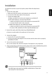
... sure both the monitor and computer are powered-OFF. b. Connect the DVI cable to diagnose the problem. HDMI 1 HDMI 2 VGA IN AUDIO IN DC IN VGA HDMI HDMI VGA AUDIO HDMI VGA DC HDMI 1 HDMI 2 VGA IN AUDIO ... outlet. 4 Turn on the monitor and computer Turn on your host system, please follow the steps below: Steps 1 Connect the video cable a Make sure both the monitor and computer are powered-OFF. b Connect one end of the monitor. 3 Connect the adapter a Connect the AC cord to the computer. Please chek user manual...
... sure both the monitor and computer are powered-OFF. b. Connect the DVI cable to diagnose the problem. HDMI 1 HDMI 2 VGA IN AUDIO IN DC IN VGA HDMI HDMI VGA AUDIO HDMI VGA DC HDMI 1 HDMI 2 VGA IN AUDIO ... outlet. 4 Turn on the monitor and computer Turn on your host system, please follow the steps below: Steps 1 Connect the video cable a Make sure both the monitor and computer are powered-OFF. b Connect one end of the monitor. 3 Connect the adapter a Connect the AC cord to the computer. Please chek user manual...
User Manual
Page 27
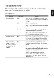
...setting on your LCD monitor for a few seconds after adjusting the size of monitor. Check if the power cord is properly connected at the back of the image before changing or disconnecting the signal cable or switching off -center, too large or too small on and in compliance which may be causing... the input signal frequency mismatch. Check if the video signal cable is properly connected to the monitor. In case of graphics adapter and monitor is switched on the screen.) Blue Remedy Using the OSD menu, ...
...setting on your LCD monitor for a few seconds after adjusting the size of monitor. Check if the power cord is properly connected at the back of the image before changing or disconnecting the signal cable or switching off -center, too large or too small on and in compliance which may be causing... the input signal frequency mismatch. Check if the video signal cable is properly connected to the monitor. In case of graphics adapter and monitor is switched on the screen.) Blue Remedy Using the OSD menu, ...
User Manual
Page 28
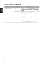
Orange Check if the video signal cable is properly connected to their default settings. English DVI/HDMI Mode (Optional) Problem No picture visible LED status Blue Off Remedy Using the OSD menu, adjust brightness and contrast to maximum or reset to the monitor. Check the power switch. Check if the AC power cord is properly connected at the back of monitor. Check if the computer system is switched on and in power saving/standby mode. 16
Orange Check if the video signal cable is properly connected to their default settings. English DVI/HDMI Mode (Optional) Problem No picture visible LED status Blue Off Remedy Using the OSD menu, adjust brightness and contrast to maximum or reset to the monitor. Check the power switch. Check if the AC power cord is properly connected at the back of monitor. Check if the computer system is switched on and in power saving/standby mode. 16


