Ferrari 3000 Service Guide
Page 7
... Advanced 36 Security 38 Boot 42 Exit 43 BIOS Flash Utility 44 System Diagnostic Diskette 44 Chapter 3 Machine Disassembly and Replacement 45 General Information 46 Before You Begin 46 Disassembly Procedure Flowchart 47 Removing the Battery Pack 50 Removing the Optical Module/HDD Module/ Wireless Lan Card and LCD... module 51 Removing the Optical Module 51 Removing the HDD Module 51 Removing the Wireless LAN Card 51 Removing the LCD Module 52 Disassembling the Main Unit 53 Remove the function key board and the keyboard 53 Separate the main unit into the logic upper and the ...
... Advanced 36 Security 38 Boot 42 Exit 43 BIOS Flash Utility 44 System Diagnostic Diskette 44 Chapter 3 Machine Disassembly and Replacement 45 General Information 46 Before You Begin 46 Disassembly Procedure Flowchart 47 Removing the Battery Pack 50 Removing the Optical Module/HDD Module/ Wireless Lan Card and LCD... module 51 Removing the Optical Module 51 Removing the HDD Module 51 Removing the Wireless LAN Card 51 Removing the LCD Module 52 Disassembling the Main Unit 53 Remove the function key board and the keyboard 53 Separate the main unit into the logic upper and the ...
Ferrari 3000 Service Guide
Page 8
Table of Contents Disassembling the External Modules 59 Disassembling the HDD Module 59 Disassembling the Optical Drive Module 59 Chapter 4 Troubleshooting 61 System Check Procedures 62 External Diskette Drive Check 62 External CD-ROM Drive Check...Locations 79 Top View 79 Bottom View 80 Chapter 6 FRU (Field Replaceable Unit) List 81 Exploded Diagram 82 Appendix A Model Definition and Configuration 90 Ferrari 3000 Series 90 Appendix B Test Compatible Components 91 Microsoft® Windows® XP Home Environment Test 92 Appendix C Online Support Information 97 Index ...
Table of Contents Disassembling the External Modules 59 Disassembling the HDD Module 59 Disassembling the Optical Drive Module 59 Chapter 4 Troubleshooting 61 System Check Procedures 62 External Diskette Drive Check 62 External CD-ROM Drive Check...Locations 79 Top View 79 Bottom View 80 Chapter 6 FRU (Field Replaceable Unit) List 81 Exploded Diagram 82 Appendix A Model Definition and Configuration 90 Ferrari 3000 Series 90 Appendix B Test Compatible Components 91 Microsoft® Windows® XP Home Environment Test 92 Appendix C Online Support Information 97 Index ...
Ferrari 3000 Service Guide
Page 53
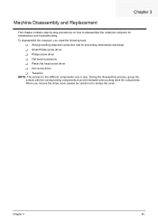
... Replacement This chapter contains step-by-step procedures on how to disassemble the notebook computer for the different components vary in size. During the disassembly process, group the screws with the corresponding components to scrape the cover. When you need the following tools: T Wrist grounding ... driver T Flat head screwdriver T Plastic flat head screw driver T Hex screw driver T Tweezers NOTE: The screws for maintenance and troubleshooting. To disassemble the computer, you remove the stripe cover, please be careful not to avoid mismatch when putting back the components.
... Replacement This chapter contains step-by-step procedures on how to disassemble the notebook computer for the different components vary in size. During the disassembly process, group the screws with the corresponding components to scrape the cover. When you need the following tools: T Wrist grounding ... driver T Flat head screwdriver T Plastic flat head screw driver T Hex screw driver T Tweezers NOTE: The screws for maintenance and troubleshooting. To disassemble the computer, you remove the stripe cover, please be careful not to avoid mismatch when putting back the components.
Ferrari 3000 Service Guide
Page 54
NOTE: Ferrari 3000 series product uses mylar or tape to fasten the FFC/FPC/connectors/cable, you may need to the system and all power and signal cables from the system. 3. Remove the battery pack. Turn off the power to tear the tape or mylar before you do the following: 1. Unplug the AC adapter and all peripherals. 2. General Information Before You Begin Before proceeding with the disassembly procedure, make sure that you disconnect different FFC/FPC/connectors. 46 Chapter 3
NOTE: Ferrari 3000 series product uses mylar or tape to fasten the FFC/FPC/connectors/cable, you may need to the system and all power and signal cables from the system. 3. Remove the battery pack. Turn off the power to tear the tape or mylar before you do the following: 1. Unplug the AC adapter and all peripherals. 2. General Information Before You Begin Before proceeding with the disassembly procedure, make sure that you disconnect different FFC/FPC/connectors. 46 Chapter 3
Ferrari 3000 Service Guide
Page 55
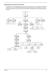
... Main Board CPU Dimm Dx3 4-in that need to remove the system board, you on the entire disassembly sequence and instructs you must first remove the keyboard, then disassemble the inside assembly frame in -1 Card Rearder Fx2 Smart Card Reader Hx1 Top Cover Shielding Tx2 HDD ...Bracket Hx2 Modem/ Bluetooth Combo Card Ex4 Thermal Module Antenna Line Modem Cable Chapter 3 47 Disassembly Procedure Flowchart The flowchart on the ...
... Main Board CPU Dimm Dx3 4-in that need to remove the system board, you on the entire disassembly sequence and instructs you must first remove the keyboard, then disassemble the inside assembly frame in -1 Card Rearder Fx2 Smart Card Reader Hx1 Top Cover Shielding Tx2 HDD ...Bracket Hx2 Modem/ Bluetooth Combo Card Ex4 Thermal Module Antenna Line Modem Cable Chapter 3 47 Disassembly Procedure Flowchart The flowchart on the ...

Ferrari 3000 Service Guide
Page 61
... the picture shows. 6. Chapter 3 53 Then take the right and the left wireless LAN antenna, then detach the logic upper assembly from the main unit. 4. Disassembling the Main Unit Remove the function key board and the keyboard 1. Disconnect function key board connector 3. Remove the three screws on the rear panel. 2.
... the picture shows. 6. Chapter 3 53 Then take the right and the left wireless LAN antenna, then detach the logic upper assembly from the main unit. 4. Disassembling the Main Unit Remove the function key board and the keyboard 1. Disconnect function key board connector 3. Remove the three screws on the rear panel. 2.
Ferrari 3000 Service Guide
Page 62
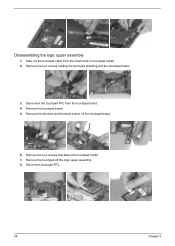
Take out the touchpad cable from the touchpad board. 4. Remove the four screws that fasten the touchpad holder. 7. Remove the wireless and bluetooth button off the logic upper assembly. 8. Disconnect touchpad FFC. 54 Chapter 3 Remove the four screws holding the touchpad shielding and the touchpad board. 3. Remove the touchpad board. 5. Disconnect the touchpad FFC from the small hook on touchpad holder. 2. Remove the touchpad off the touchpad board. 6. Disassembling the logic upper assembly 1.
Take out the touchpad cable from the touchpad board. 4. Remove the four screws that fasten the touchpad holder. 7. Remove the wireless and bluetooth button off the logic upper assembly. 8. Disconnect touchpad FFC. 54 Chapter 3 Remove the four screws holding the touchpad shielding and the touchpad board. 3. Remove the touchpad board. 5. Disconnect the touchpad FFC from the small hook on touchpad holder. 2. Remove the touchpad off the touchpad board. 6. Disassembling the logic upper assembly 1.
Ferrari 3000 Service Guide
Page 63
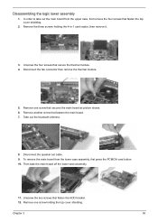
... four screws that fasten the top cover shielding. 2. Unscrew the two screws that fastens the main board. 7. Remove one screw that secure the thermal module. 4. Disassembling the logic lower assembly 1. Disconnect the fan connector then remove the thermal module. 5. Remove another screw that fasten the HDD bracket. 12. Then take out...
... four screws that fasten the top cover shielding. 2. Unscrew the two screws that fastens the main board. 7. Remove one screw that secure the thermal module. 4. Disassembling the logic lower assembly 1. Disconnect the fan connector then remove the thermal module. 5. Remove another screw that fasten the HDD bracket. 12. Then take out...

Ferrari 3000 Service Guide
Page 65
... six screw pad and the six screws. 2. Disconnect the LCD coaxial cable. . 10. Tear off the electric conductive tape that fastens the LCD coaxial cable. 9. Disassembling the LCD Module 1. Remove the LCD latch kit bracket. Remove the four screws that fasten the right and the left LCD brackets. 7. Detach the wireless...
... six screw pad and the six screws. 2. Disconnect the LCD coaxial cable. . 10. Tear off the electric conductive tape that fastens the LCD coaxial cable. 9. Disassembling the LCD Module 1. Remove the LCD latch kit bracket. Remove the four screws that fasten the right and the left LCD brackets. 7. Detach the wireless...

Ferrari 3000 Service Guide
Page 67
... door. Remove the three screws that fasten the ODD door. 8. Remove the two screws holding the HDD bracket; Then remove the optical bracket. 6. Disassembling the Optical Drive Module 1. Chapter 3 59 Then remove the last two screws on each side. 2. Slide the ODD from the HDD bracket. two ...on the back side of the ODD module. 4. Disassembling the External Modules Disassembling the HDD Module 1. Remove the four screws holding the ODD bracket. 2. In order to open the ODD, use an uncurved pin to...
... door. Remove the three screws that fasten the ODD door. 8. Remove the two screws holding the HDD bracket; Then remove the optical bracket. 6. Disassembling the Optical Drive Module 1. Chapter 3 59 Then remove the last two screws on each side. 2. Slide the ODD from the HDD bracket. two ...on the back side of the ODD module. 4. Disassembling the External Modules Disassembling the HDD Module 1. Remove the four screws holding the ODD bracket. 2. In order to open the ODD, use an uncurved pin to...
Ferrari 3000 Service Guide
Page 69
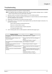
...POST detects an error and displayed messages on page 77 Chapter 4 61 Chapter 4 Troubleshooting Use the following procedure as possible. 2. Non-Acer products, prototype cards, or modified options can perform visual inspection before you fellow this model. there are no obviously burned or heated ...components; No beep or error codes are properly connected and secured; there are no obvious shorts or opens; Disassemble and assemble the unit without any problem occurs, you can give false errors and invalid system responses. 1. LCD display problems or...
...POST detects an error and displayed messages on page 77 Chapter 4 61 Chapter 4 Troubleshooting Use the following procedure as possible. 2. Non-Acer products, prototype cards, or modified options can perform visual inspection before you fellow this model. there are no obviously burned or heated ...components; No beep or error codes are properly connected and secured; there are no obvious shorts or opens; Disassemble and assemble the unit without any problem occurs, you can give false errors and invalid system responses. 1. LCD display problems or...


