
Aspire T310 User Guide
Page 12
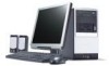
This section provides a brief description of speakers (optional). Connect the mouse to the PS/2 keyboard port or USB port on the back panel of the system. Mouse(PS/2 or USB, manufacturing option) The included mouse is a standard two-button wheel mouse. Keyboard(PS/2 or USB, manufacturing option) Connect the keyboard to the PS/2 mouse port or USB port on the back panel of the system. English 4 System Tour System peripherals The Aspire T310 computer consists the system itself, and system peripherals, like a mouse, a keyboard and a set of basic system peripherals.
This section provides a brief description of speakers (optional). Connect the mouse to the PS/2 keyboard port or USB port on the back panel of the system. Mouse(PS/2 or USB, manufacturing option) The included mouse is a standard two-button wheel mouse. Keyboard(PS/2 or USB, manufacturing option) Connect the keyboard to the PS/2 mouse port or USB port on the back panel of the system. English 4 System Tour System peripherals The Aspire T310 computer consists the system itself, and system peripherals, like a mouse, a keyboard and a set of basic system peripherals.

Aspire T310 User Guide
Page 15
...-out jacks (one at front and one at rear panel) and a stereo line-in any location that is excessively dusty or damp. Your Aspire T310 has standard I / O ports. Open package Open the package carefully and keep all packing materials for your computer: • Don't place the system ...too close to setting up your Aspire T310 System: • Select a location • Open package Select location Selecting the optimum location for later use. The system...
...-out jacks (one at front and one at rear panel) and a stereo line-in any location that is excessively dusty or damp. Your Aspire T310 has standard I / O ports. Open package Open the package carefully and keep all packing materials for your computer: • Don't place the system ...too close to setting up your Aspire T310 System: • Select a location • Open package Select location Selecting the optimum location for later use. The system...
Power F1/ Aspire T310 Service Guide
Page 12
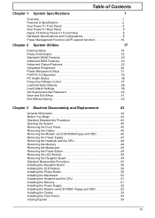
...1 Features & Specification 2 Acer Power F1 Front Panel 4 Acer Power F1 Rear Panel 5 Aspire T310/Acer Power F1 Front Panel 6 Hardware Specifications and Configurations 8 Power Management Function (ACPI support function 16 Chapter 2 System Utilities 17 Entering Setup 18 Product Information 19 Standard CMOS Features 20 Advanced BIOS ...Removing the Mainboard 49 Removing the Power Button 49 Removing the LED Module 49 Removing the Daughter Board 49 Standard Reassembly Procedure 50 Installing the Daughter Board 50 Installing the LED Module 50 Installing the Power Button 50 ...
...1 Features & Specification 2 Acer Power F1 Front Panel 4 Acer Power F1 Rear Panel 5 Aspire T310/Acer Power F1 Front Panel 6 Hardware Specifications and Configurations 8 Power Management Function (ACPI support function 16 Chapter 2 System Utilities 17 Entering Setup 18 Product Information 19 Standard CMOS Features 20 Advanced BIOS ...Removing the Mainboard 49 Removing the Power Button 49 Removing the LED Module 49 Removing the Daughter Board 49 Standard Reassembly Procedure 50 Installing the Daughter Board 50 Installing the LED Module 50 Installing the Power Button 50 ...
Power F1/ Aspire T310 Service Guide
Page 19
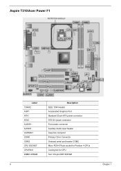
Aspire T310/Acer Power F1 Label 1394A2 AGP1 ATX1 ATX2 AUDIO1 AUXIN1 CASFAN1 CDIN1 COM2 CPU SOCKET CPUFAN1 DIMM1-DIMM2 Description IEEE 1394 Header Accelerated Graphics Port Standard 20-pin ATX power connector ATX12V power connector Front audio connector Auxiliary Audio input header Case fan connector Primary CD-in Connector Onboard serial port header COM2 Micro PGA 478-pin socket for Pentium 4 CPUs Cooling fan for CPU Two 184-pin DDR SDRAM 6 Chapter 1
Aspire T310/Acer Power F1 Label 1394A2 AGP1 ATX1 ATX2 AUDIO1 AUXIN1 CASFAN1 CDIN1 COM2 CPU SOCKET CPUFAN1 DIMM1-DIMM2 Description IEEE 1394 Header Accelerated Graphics Port Standard 20-pin ATX power connector ATX12V power connector Front audio connector Auxiliary Audio input header Case fan connector Primary CD-in Connector Onboard serial port header COM2 Micro PGA 478-pin socket for Pentium 4 CPUs Cooling fan for CPU Two 184-pin DDR SDRAM 6 Chapter 1
Power F1/ Aspire T310 Service Guide
Page 29
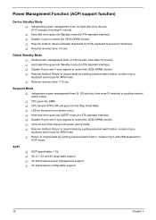
...method: Return to original state by pushing external switch button, modem ring in , keyboard and mouse for ATA standard interface). T CPU goes into SLEEP mode (for ATA standard interface). T On board device configuration support. 16 Chapter 1 T CPU asserts STPCLK# and goes into power...ACPI support function) Device Standby Mode T Independent power management timer for Windows). T Hard disk drive goes into Standby mode (for ATA standard interface). T On board device power management support. T Hard disk drive goes into Standby mode (for APM mode. ACPI T ACPI ...
...method: Return to original state by pushing external switch button, modem ring in , keyboard and mouse for ATA standard interface). T CPU goes into SLEEP mode (for ATA standard interface). T On board device configuration support. 16 Chapter 1 T CPU asserts STPCLK# and goes into power...ACPI support function) Device Standby Mode T Independent power management timer for Windows). T Hard disk drive goes into Standby mode (for ATA standard interface). T On board device power management support. T Hard disk drive goes into Standby mode (for APM mode. ACPI T ACPI ...

Power F1/ Aspire T310 Service Guide
Page 33
To enter the IDE Channel 0 Slave setup, press [Enter]. The following screen shows the Standard CMOS Features menu: The following the hour-minutesecond format Allows you to configure the hard disk drive connected to the master port of IDE channel 0. ... are the default and suggested settings. To enter the IDE Channel 0 Master setup, press [Enter]. The IDE CD-ROM is always automatically detected. Standard CMOS Features Select Standard CMOS Features from the main menu to 59 IDE Device Model Number: None IDE Device Model Number: None 20 Chapter 2 Settings in this menu...
To enter the IDE Channel 0 Slave setup, press [Enter]. The following screen shows the Standard CMOS Features menu: The following the hour-minutesecond format Allows you to configure the hard disk drive connected to the master port of IDE channel 0. ... are the default and suggested settings. To enter the IDE Channel 0 Master setup, press [Enter]. The IDE CD-ROM is always automatically detected. Standard CMOS Features Select Standard CMOS Features from the main menu to 59 IDE Device Model Number: None IDE Device Model Number: None 20 Chapter 2 Settings in this menu...

Power F1/ Aspire T310 Service Guide
Page 34
... almost useless and may be disregarded in case of Power On Self Test errors (POST). Everything above and beyond the standard 1MB of base memory that is available to standard DOS programs. DOS systems have an address space od 1MB, but the top 384KB (called high memory) is therefore ... Allows you to configure the hard disk drive connected to the master port of IDE channel 1. Since current PCs use . Memory above 1MB is the standard Japanese floppy drive mode. Chapter 2 21 IDE Device Model Number: None Allows you to configure your floppy drive B. 1.44 MB, 3.5-inch None 360 KB...
... almost useless and may be disregarded in case of Power On Self Test errors (POST). Everything above and beyond the standard 1MB of base memory that is available to standard DOS programs. DOS systems have an address space od 1MB, but the top 384KB (called high memory) is therefore ... Allows you to configure the hard disk drive connected to the master port of IDE channel 1. Since current PCs use . Memory above 1MB is the standard Japanese floppy drive mode. Chapter 2 21 IDE Device Model Number: None Allows you to configure your floppy drive B. 1.44 MB, 3.5-inch None 360 KB...
Power F1/ Aspire T310 Service Guide
Page 42
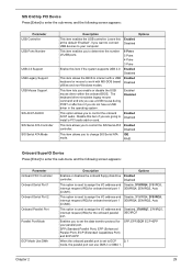
... used to assign the I/O address and Disable, 3F8/IRQ4, 2F8/IRQ3, interrupt request (IRQ) for onboard serial port 1 3E8/IRQ4, 2E8/IRQ3, Auto (COM1). SPP (Standard Parallel Port), EPP (Enhanced Parallel Port), ECP (Extended Capabilities Port) and ECP+EPP. This item allows you to control the SiS Serial ATA Enabled controller...
... used to assign the I/O address and Disable, 3F8/IRQ4, 2F8/IRQ3, interrupt request (IRQ) for onboard serial port 1 3E8/IRQ4, 2E8/IRQ3, Auto (COM1). SPP (Standard Parallel Port), EPP (Enhanced Parallel Port), ECP (Extended Capabilities Port) and ECP+EPP. This item allows you to control the SiS Serial ATA Enabled controller...

Power F1/ Aspire T310 Service Guide
Page 58
Opening the System 1. Place the system unit on a flat, steady surface. 2. Remove the bezel by following the instruction below. Removing the Cables 1. Standard Disassembly Procedure This section tells you how to disassemble the system when you have turned off the system and all peripherals connected to it . Please ...
Opening the System 1. Place the system unit on a flat, steady surface. 2. Remove the bezel by following the instruction below. Removing the Cables 1. Standard Disassembly Procedure This section tells you how to disassemble the system when you have turned off the system and all peripherals connected to it . Please ...

Power F1/ Aspire T310 Service Guide
Page 63
... with one screw as shown here. Installing the Mainboard 1. Put the motherboard to the daughter board. 2. Install the LED module by following the instructions here. Standard Reassembly Procedure This section tells you how to reassemble the system when you need to the assembly video, if available. Please also refer to perform...
... with one screw as shown here. Installing the Mainboard 1. Put the motherboard to the daughter board. 2. Install the LED module by following the instructions here. Standard Reassembly Procedure This section tells you how to reassemble the system when you need to the assembly video, if available. Please also refer to perform...

Power F1/ Aspire T310 Service Guide
Page 86
.... Refer to SJ1. Connect the case LED cable to the following: Description 1. Connect the Pentium 4 processor auxiliary case power supply connector to ATX1. 6. Connect the standard power supply connector to ATX2. Connect the CPU cooling fan cable to CASFAN1. 3. Connect the case cooling fan connector to CPUFAN1. 2. Connect the Northbridge cooling...
.... Refer to SJ1. Connect the case LED cable to the following: Description 1. Connect the Pentium 4 processor auxiliary case power supply connector to ATX1. 6. Connect the standard power supply connector to ATX2. Connect the CPU cooling fan cable to CASFAN1. 3. Connect the case cooling fan connector to CPUFAN1. 2. Connect the Northbridge cooling...

Power F1/ Aspire T310 Service Guide
Page 88
... on/off signal, at least 50ms to signal the power supply to the onboard IDE interface. Front Panel Connector The front panel connect (PANEL 1) provides a standard set of switch and LED connectors commonly found on /off signal. When the switch is being read from or written to a signal- Chapter 5 75 Refer...
... on/off signal, at least 50ms to signal the power supply to the onboard IDE interface. Front Panel Connector The front panel connect (PANEL 1) provides a standard set of switch and LED connectors commonly found on /off signal. When the switch is being read from or written to a signal- Chapter 5 75 Refer...