Service Guide
Page 7
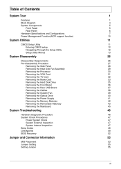
... the Cables Removing the System Fan Removing the Optical Drive Removing the Power Supply Removing the Memory Modules Removing the Removable HDD bay Removing the Mainboard 26 26 27 28 29 30 31 32 33 35 36 37 38 39 40 41 42 43 45 System Troubleshooting Hardware Diagnostic Procedure System...
... the Cables Removing the System Fan Removing the Optical Drive Removing the Power Supply Removing the Memory Modules Removing the Removable HDD bay Removing the Mainboard 26 26 27 28 29 30 31 32 33 35 36 37 38 39 40 41 42 43 45 System Troubleshooting Hardware Diagnostic Procedure System...

Service Guide
Page 29
Option Enabled Disabled Enabled Disabled Chapter 2 21 Frequency/Voltage Control Parameter Clock to All DIMM/PCI Spread Spectrum Description Enables or disables control the clock to lock up. A slight jitter can introduce a temporary boost in clock speed causing the overclocked processor to all DIMM/PCI Enables or disables the reduction of the mainboard's EMI. Note: Remember to disable the Spread Spectrum feature if you are overclocking.
Option Enabled Disabled Enabled Disabled Chapter 2 21 Frequency/Voltage Control Parameter Clock to All DIMM/PCI Spread Spectrum Description Enables or disables control the clock to lock up. A slight jitter can introduce a temporary boost in clock speed causing the overclocked processor to all DIMM/PCI Enables or disables the reduction of the mainboard's EMI. Note: Remember to disable the Spread Spectrum feature if you are overclocking.

Service Guide
Page 37
Use a long-nosed screwdriver to loosen the four screws on . NEVER touch the heat sink with any metal or with your hands. 1. Lift the heat sink fan assembly away from the mainboard. 2. Removing the Heat Sink Fan Assembly WARNING:The heat sink becomes very hot when the system is on the heat sink, in the order as shown below. 3. disconnect the fan cable from the mainboard. 29 Chapter 3
Use a long-nosed screwdriver to loosen the four screws on . NEVER touch the heat sink with any metal or with your hands. 1. Lift the heat sink fan assembly away from the mainboard. 2. Removing the Heat Sink Fan Assembly WARNING:The heat sink becomes very hot when the system is on the heat sink, in the order as shown below. 3. disconnect the fan cable from the mainboard. 29 Chapter 3

Service Guide
Page 38
Release the load lever. 2. 3. WARNING:The processor becomes very hot when the system is properly oriented over the socket. Pull out the processor from the mainboard, make sure the processor is on the corner to cool off first before handling. 1. Lift the load lever and load plate to create a backup file of all important data. Removing the Processor IMPORTANT:Before removing a processor from the socket. Allow it to make sure to the fully open, upright position (1) and (2). IMPORTANT: If you are going to install a new processor, note the arrow on . Chapter 3 30
Release the load lever. 2. 3. WARNING:The processor becomes very hot when the system is properly oriented over the socket. Pull out the processor from the mainboard, make sure the processor is on the corner to cool off first before handling. 1. Lift the load lever and load plate to create a backup file of all important data. Removing the Processor IMPORTANT:Before removing a processor from the socket. Allow it to make sure to the fully open, upright position (1) and (2). IMPORTANT: If you are going to install a new processor, note the arrow on . Chapter 3 30

Service Guide
Page 39
One finger Press the clip and the same time Gently pull the card to remove it from the VGA card. 4. Disconnect the power cables from the mainboard. 31 Chapter 3 Removing the VGA Card 1. Release the Slot cover lock. 2. 3. Remove the screw from chassis.
One finger Press the clip and the same time Gently pull the card to remove it from the VGA card. 4. Disconnect the power cables from the mainboard. 31 Chapter 3 Removing the VGA Card 1. Release the Slot cover lock. 2. 3. Remove the screw from chassis.

Service Guide
Page 40
Chapter 3 32 Removing the TV Card 1. Gently pull the TV card to remove it from the mainboard.
Chapter 3 32 Removing the TV Card 1. Gently pull the TV card to remove it from the mainboard.

Service Guide
Page 41
Removing the Mode Card 1. Gently pull the Mode card to remove it from the mainboard. 33 Chapter 3
Removing the Mode Card 1. Gently pull the Mode card to remove it from the mainboard. 33 Chapter 3

Service Guide
Page 42
Lift the bracket up and turn it over. Removing the Hard Disk Drive 1. Remove the HDD bracket a. b. Remove the screw that secures the HDD bracket to the ODD bracket. Disconnect the data and power cables from the rear of the optical drive and the mainboard. 2. Chapter 3 34
Lift the bracket up and turn it over. Removing the Hard Disk Drive 1. Remove the HDD bracket a. b. Remove the screw that secures the HDD bracket to the ODD bracket. Disconnect the data and power cables from the rear of the optical drive and the mainboard. 2. Chapter 3 34

Service Guide
Page 49
Removing the Power Supply 1. Remove the four screw that secures the power supply to the chassis. 3. Lift the power supply module out of the chassis. 41 Chapter 3 Disconnect the 24-pin and 4-pin power supply cables from the mainboard. 2.
Removing the Power Supply 1. Remove the four screw that secures the power supply to the chassis. 3. Lift the power supply module out of the chassis. 41 Chapter 3 Disconnect the 24-pin and 4-pin power supply cables from the mainboard. 2.

Service Guide
Page 52
Note:Circuit boards >10 cm² has been highlighted with the yellow rectangle as above image shows. Please detach the Circuit boards and follow local regulations for disposal. Remove the eight screws that secure the mainboard to the chassis. Chapter 3 44 Removing the Mainboard 1.
Note:Circuit boards >10 cm² has been highlighted with the yellow rectangle as above image shows. Please detach the Circuit boards and follow local regulations for disposal. Remove the eight screws that secure the mainboard to the chassis. Chapter 3 44 Removing the Mainboard 1.
Service Guide
Page 63
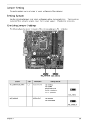
... Chapter 5 55 Jumpers with more Than one pin are Placed on the correct pins. Checking Jumper Settings The following illustration shows the location of the mainboard. Jumper CLR_CMOSCLR_CMOS Type 3-pin Description CLEAR CMOS Setting (default) 1-2: NORMAL 2-3: CLEAR Before clearing the CMOS, make sure to set system configuration options. Pin 1 is labeled...
... Chapter 5 55 Jumpers with more Than one pin are Placed on the correct pins. Checking Jumper Settings The following illustration shows the location of the mainboard. Jumper CLR_CMOSCLR_CMOS Type 3-pin Description CLEAR CMOS Setting (default) 1-2: NORMAL 2-3: CLEAR Before clearing the CMOS, make sure to set system configuration options. Pin 1 is labeled...

