Service Guide
Page 7
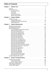
Table of Contents Chapter 1 System Tour 1 Features 1 Aspire G7710 Tour 3 Closed Front Panel 3 Front Panel 4 Rear Panel 5 Internal Components 6 System LED Indicators 7 Chapter 2 System Utilities 9 CMOS Setup Utility 9 Entering CMOS setup 10 Navigating ... the Processor 52 Removing the Power Supply 54 Removing the HDD Fan 56 Removing the Top Cover 57 Removing the USB Board 58 Removing the Mainboard 60 Removing the Front Foot Stand 62 Removing the Rear Foot Stand 63 Hardware Diagnostic Procedure 65 Chapter 4 System Troubleshooting 65 System Check Procedures 66...
Table of Contents Chapter 1 System Tour 1 Features 1 Aspire G7710 Tour 3 Closed Front Panel 3 Front Panel 4 Rear Panel 5 Internal Components 6 System LED Indicators 7 Chapter 2 System Utilities 9 CMOS Setup Utility 9 Entering CMOS setup 10 Navigating ... the Processor 52 Removing the Power Supply 54 Removing the HDD Fan 56 Removing the Top Cover 57 Removing the USB Board 58 Removing the Mainboard 60 Removing the Front Foot Stand 62 Removing the Rear Foot Stand 63 Hardware Diagnostic Procedure 65 Chapter 4 System Troubleshooting 65 System Check Procedures 66...
Service Guide
Page 8
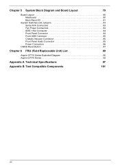
Chapter 5 System Block Diagram and Board Layout 79 Board Layout 80 Mainboard 80 Back Panel I/O 81 System Switches and Jumpers 83 Serial ATA Connectors 83 Fan Power Connectors 83 IEEE 1394 Connector 84 Front Panel Connector 84 Front USB Connector 85 Chassis Intrusion Connector 85 Front Panel Auido Connector 85 Power Connectors 86 CMOS Reset Button 87 Chapter 6 FRU (Field Replaceable Unit) List 89 Aspire G7710 Series Exploded Diagram 90 Aspire G7710 Series 92 Appendix A Technical Specifications 97 Appendix B Test Compatible Components 101 viii
Chapter 5 System Block Diagram and Board Layout 79 Board Layout 80 Mainboard 80 Back Panel I/O 81 System Switches and Jumpers 83 Serial ATA Connectors 83 Fan Power Connectors 83 IEEE 1394 Connector 84 Front Panel Connector 84 Front USB Connector 85 Chassis Intrusion Connector 85 Front Panel Auido Connector 85 Power Connectors 86 CMOS Reset Button 87 Chapter 6 FRU (Field Replaceable Unit) List 89 Aspire G7710 Series Exploded Diagram 90 Aspire G7710 Series 92 Appendix A Technical Specifications 97 Appendix B Test Compatible Components 101 viii

Service Guide
Page 15
Internal Components Item 1 2 3 4 5 6 7 8 9 10 Component Liquid cooling system Mainboard System memory Release sliders for optical drives Hard drive backplane board Release sliders for HDD drives Expansion slot lock levers Expansion card System fan Power supply module Chapter 1 7
Internal Components Item 1 2 3 4 5 6 7 8 9 10 Component Liquid cooling system Mainboard System memory Release sliders for optical drives Hard drive backplane board Release sliders for HDD drives Expansion slot lock levers Expansion card System fan Power supply module Chapter 1 7
Service Guide
Page 28
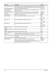
... of stability on the system. A slight jitter can introduce a temporary boost in clock speed causing the overclocked processor to provide the best level of the mainboard's EMI. Auto Min: 1.200v Max: 1.600 V SB Voltage (V) Select Southbridge (SB) chipset voltage control. NB GTL Reference Voltage Set the NB GTL reference voltage to...
... of stability on the system. A slight jitter can introduce a temporary boost in clock speed causing the overclocked processor to provide the best level of the mainboard's EMI. Auto Min: 1.200v Max: 1.600 V SB Voltage (V) Select Southbridge (SB) chipset voltage control. NB GTL Reference Voltage Set the NB GTL reference voltage to...
Service Guide
Page 37
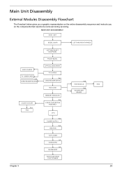
... CARD READER DRIVE HDD CAGE MEMORY MODULES Ex4 LIQUID COOLER FAN ASSEMBLY CPU Gx4 POWER SUPPLY Hx4 HDD FAN TOP COVER Ix2 USB BOARD Jx6 MAINBOARD FRONT AND REAR FOOT STANDS Ax4 HDD MODULE Dx2 BACKPLANE BOARD HDD Chapter 3 29 Main Unit Disassembly External Modules Disassembly Flowchart The flowchart below gives...
... CARD READER DRIVE HDD CAGE MEMORY MODULES Ex4 LIQUID COOLER FAN ASSEMBLY CPU Gx4 POWER SUPPLY Hx4 HDD FAN TOP COVER Ix2 USB BOARD Jx6 MAINBOARD FRONT AND REAR FOOT STANDS Ax4 HDD MODULE Dx2 BACKPLANE BOARD HDD Chapter 3 29 Main Unit Disassembly External Modules Disassembly Flowchart The flowchart below gives...

Service Guide
Page 44
Removing the Front Bezel 1. Release the front bezel retention tabs from the mainboard. 4. Disconnect the front panel cable from the chassis interior. 36 Chapter 3 See "Removing the Bezel Door" on page 34. 3. See "Removing the Left Side Panel" on page 31. 2.
Removing the Front Bezel 1. Release the front bezel retention tabs from the mainboard. 4. Disconnect the front panel cable from the chassis interior. 36 Chapter 3 See "Removing the Bezel Door" on page 34. 3. See "Removing the Left Side Panel" on page 31. 2.

Service Guide
Page 47
See "Removing the Bezel Door" on its side (with components showing). 4. Lay the system on page 31. 2. Remove the SLI bridge cable from the mainboard. 6. Chapter 3 39 Gently pull the card to the other card. Do the same to detach it from the video cards, then press down on page 34. 3. Removing the Video Cards 1. See "Removing the Left Side Panel" on the expansion slot release latch. 5.
See "Removing the Bezel Door" on its side (with components showing). 4. Lay the system on page 31. 2. Remove the SLI bridge cable from the mainboard. 6. Chapter 3 39 Gently pull the card to the other card. Do the same to detach it from the video cards, then press down on page 34. 3. Removing the Video Cards 1. See "Removing the Left Side Panel" on the expansion slot release latch. 5.

Service Guide
Page 49
Removing the TV Tuner Card 1. See "Removing the Video Cards" on the expansion slot release latch. 5. Chapter 3 41 Press down on page 39. 4. See "Removing the Left Side Panel" on page 31. 2. Gently pull the card to detach it from the mainboard. See "Removing the Bezel Door" on page 34. 3.
Removing the TV Tuner Card 1. See "Removing the Video Cards" on the expansion slot release latch. 5. Chapter 3 41 Press down on page 39. 4. See "Removing the Left Side Panel" on page 31. 2. Gently pull the card to detach it from the mainboard. See "Removing the Bezel Door" on page 34. 3.

Service Guide
Page 50
See "Removing the Bezel Door" on page 34. 3. See "Removing the Left Side Panel" on page 31. 2. Release cables from the mainboard. 42 Chapter 3 Disconnect the USB and 1394 cables from the retention clip. 5. See "Removing the Front Bezel" on page 36. 4. Removing the Card Reader Drive 1.
See "Removing the Bezel Door" on page 34. 3. See "Removing the Left Side Panel" on page 31. 2. Release cables from the mainboard. 42 Chapter 3 Disconnect the USB and 1394 cables from the retention clip. 5. See "Removing the Front Bezel" on page 36. 4. Removing the Card Reader Drive 1.

Service Guide
Page 56
Press the holding clips on page 31. 2. Gently pull the DIMM upward and to pull it away from the memory board, make sure to create a backup file of the DIMM slot outward to release the DIMM. 4. Removing the Memory Modules IMPORTANT:Before removing any DIMM from the mainboard. 48 Chapter 3 See "Removing the Bezel Door" on both sides of all important data. 1. See "Removing the Left Side Panel" on page 34. 3.
Press the holding clips on page 31. 2. Gently pull the DIMM upward and to pull it away from the memory board, make sure to create a backup file of the DIMM slot outward to release the DIMM. 4. Removing the Memory Modules IMPORTANT:Before removing any DIMM from the mainboard. 48 Chapter 3 See "Removing the Bezel Door" on both sides of all important data. 1. See "Removing the Left Side Panel" on page 34. 3.

Service Guide
Page 58
Lift the fan and heat exchanger end of the liquid cooler fan assembly to the chassis. Do not let the thermal patch touch the work surface. 9. 6. N/A 7. Screw (Quantity) Liquid cooler screw (4) Color Black Torque 4.5 to wipe off the thermal grease from the mainboard. 8. Use an alcohol pad to 5.5 kgf-cm Part No. Remove the four screws (E) securing the fan end of the liquid cooler assembly from the chassis, then gently detach the cooler end from both the liquid cooler and the processor. 50 Chapter 3 Lay cooler on its side-with the thermal patch facing sideways.
Lift the fan and heat exchanger end of the liquid cooler fan assembly to the chassis. Do not let the thermal patch touch the work surface. 9. 6. N/A 7. Screw (Quantity) Liquid cooler screw (4) Color Black Torque 4.5 to wipe off the thermal grease from the mainboard. 8. Use an alcohol pad to 5.5 kgf-cm Part No. Remove the four screws (E) securing the fan end of the liquid cooler assembly from the chassis, then gently detach the cooler end from both the liquid cooler and the processor. 50 Chapter 3 Lay cooler on its side-with the thermal patch facing sideways.

Service Guide
Page 60
Allow it to release load lever. 6. See "Removing the Bezel Door" on page 49. 5. See "Removing the Liquid Cooler Fan Assembly" on page 31. 2. Press down to cool off first before handling. 1. See "Removing the Memory Modules" on page 34. 3. See "Removing the Left Side Panel" on page 48. 4. Lift the load lever up and open the load plate. 52 Chapter 3 Removing the Processor IMPORTANT:Before removing a processor from the mainboard, make sure to create a backup file of all important data. WARNING:The processor becomes very hot when the system is on.
Allow it to release load lever. 6. See "Removing the Bezel Door" on page 49. 5. See "Removing the Liquid Cooler Fan Assembly" on page 31. 2. Press down to cool off first before handling. 1. See "Removing the Memory Modules" on page 34. 3. See "Removing the Left Side Panel" on page 48. 4. Lift the load lever up and open the load plate. 52 Chapter 3 Removing the Processor IMPORTANT:Before removing a processor from the mainboard, make sure to create a backup file of all important data. WARNING:The processor becomes very hot when the system is on.

Service Guide
Page 62
... Door" on page 39. 6. See "Removing the Video Cards" on page 31. 2. See "Removing the Backplane Board" on page 38. 5. Release the cables from the mainboard. 54 Chapter 3 See "Removing the Optical Drive" on page 46. 9. See "Removing the Memory Modules" on page 52. 12. See "Removing the Processor" on page...
... Door" on page 39. 6. See "Removing the Video Cards" on page 31. 2. See "Removing the Backplane Board" on page 38. 5. Release the cables from the mainboard. 54 Chapter 3 See "Removing the Optical Drive" on page 46. 9. See "Removing the Memory Modules" on page 52. 12. See "Removing the Processor" on page...

Service Guide
Page 64
Remove the fan from the mainboard. 6. Screw (Quantity) M#6-32 L20 BZN (4) Color Black 7. Torque N/A Part No. 86.00J10.A60 56 Chapter 3 See "Removing the Card Reader Drive" on page 31. 2. See "Removing the Bezel Door" on page 42. 5. Remove the four screws (H) that secure the fan to the chassis. See "Removing the Front Bezel" on page 34. 3. Removing the HDD Fan 1. See "Removing the Left Side Panel" on page 36. 4. Disconnect the fan cable from the chassis.
Remove the fan from the mainboard. 6. Screw (Quantity) M#6-32 L20 BZN (4) Color Black 7. Torque N/A Part No. 86.00J10.A60 56 Chapter 3 See "Removing the Card Reader Drive" on page 31. 2. See "Removing the Bezel Door" on page 42. 5. Remove the four screws (H) that secure the fan to the chassis. See "Removing the Front Bezel" on page 34. 3. Removing the HDD Fan 1. See "Removing the Left Side Panel" on page 36. 4. Disconnect the fan cable from the chassis.

Service Guide
Page 66
See "Removing the Card Reader Drive" on page 52. 10. Detach the USB and audio cables from the mainboard. 13. See "Removing the Processor" on page 42. 6. See "Removing the Video Cards" on page 41. 5. See "Removing the TV Tuner Card" on page 39. 4. ...
See "Removing the Card Reader Drive" on page 52. 10. Detach the USB and audio cables from the mainboard. 13. See "Removing the Processor" on page 42. 6. See "Removing the Video Cards" on page 41. 5. See "Removing the TV Tuner Card" on page 39. 4. ...

Service Guide
Page 68
... TV Tuner Card" on page 39. 4. See "Removing the Video Cards" on page 41. 5. See "Removing the Power Supply" on page 38. 3. Removing the Mainboard 1. See "Removing the Optical Drive" on page 54. 11. See "Removing the Processor" on page 46. 7. See "Removing the Backplane Board" on page 52..... 12. See "Removing the Top Cover" on page 48. 8. See "Removing the Memory Modules" on page 57. 13. Disconnect the LED cable from the mainboard. 60 Chapter 3 See "Removing the Bezel Door" on page 58. 14. See "Removing the USB Board" on page 31. 2. See "Removing the Liquid ...
... TV Tuner Card" on page 39. 4. See "Removing the Video Cards" on page 41. 5. See "Removing the Power Supply" on page 38. 3. Removing the Mainboard 1. See "Removing the Optical Drive" on page 54. 11. See "Removing the Processor" on page 46. 7. See "Removing the Backplane Board" on page 52..... 12. See "Removing the Top Cover" on page 48. 8. See "Removing the Memory Modules" on page 57. 13. Disconnect the LED cable from the mainboard. 60 Chapter 3 See "Removing the Bezel Door" on page 58. 14. See "Removing the USB Board" on page 31. 2. See "Removing the Liquid ...

Service Guide
Page 69
Torque 4.5 to the chassis, in the order shown. Screw (Quantity) HEX #6-32 5MM NI (6) Color Silver 16. Remove the nine screws (J) that secure the mainboard to 5.5 kgf-cm Part No. 86.2G5B6.013 Chapter 3 61 Lift the board from the chassis. 15.
Torque 4.5 to the chassis, in the order shown. Screw (Quantity) HEX #6-32 5MM NI (6) Color Silver 16. Remove the nine screws (J) that secure the mainboard to 5.5 kgf-cm Part No. 86.2G5B6.013 Chapter 3 61 Lift the board from the chassis. 15.

