Acer Aspire 8940 Service Guide
Page 7
... 8 Right View 9 Bottom View 10 TouchPad Basics 11 Using the Keyboard 12 Key Types 12 Windows Keys 13 System Hotkeys 14 Using the System Utilities 15 Acer GridVista (dual-display compatible 15 Hardware Specifications and Configurations 16 System Utilities...Removing the Primary Hard Disk Drive Module 58 Removing the Secondary Hard Disk Drive Module 60 Removing the DIMM Modules 62 Removing the TV Tuner Module 63 Removing the WLAN Module 65 Main Unit Disassembly Process 67 Upper Cover Disassembly Flowchart 67 Lower Cover Disassembly Flowchart 68 Removing the Keyboard 69 Removing...
... 8 Right View 9 Bottom View 10 TouchPad Basics 11 Using the Keyboard 12 Key Types 12 Windows Keys 13 System Hotkeys 14 Using the System Utilities 15 Acer GridVista (dual-display compatible 15 Hardware Specifications and Configurations 16 System Utilities...Removing the Primary Hard Disk Drive Module 58 Removing the Secondary Hard Disk Drive Module 60 Removing the DIMM Modules 62 Removing the TV Tuner Module 63 Removing the WLAN Module 65 Main Unit Disassembly Process 67 Upper Cover Disassembly Flowchart 67 Lower Cover Disassembly Flowchart 68 Removing the Keyboard 69 Removing...
Acer Aspire 8940 Service Guide
Page 9
... the Upper Case 172 Replacing the LCD Module 175 Replacing the Power Board 179 Removing the Switch Cover 180 Replacing the Keyboard 182 External Module Reassembly Instructions 184 Replacing the WLAN Module 184 Replacing the TV ...On Issue 192 No Display Issue 193 Random Loss of BIOS Settings 194 LCD Failure 195 Built-In Keyboard Failure 196 TouchPad Failure 197 Internal Speaker Failure 198 Internal Microphone Failure 199 HDD Not Operating Correctly 200...by Crisis Disk 210 FRU (Field Replaceable Unit) List 211 Aspire 8940 Exploded Diagrams 212 Main Chassis 212 LCD Assembly 213...
... the Upper Case 172 Replacing the LCD Module 175 Replacing the Power Board 179 Removing the Switch Cover 180 Replacing the Keyboard 182 External Module Reassembly Instructions 184 Replacing the WLAN Module 184 Replacing the TV ...On Issue 192 No Display Issue 193 Random Loss of BIOS Settings 194 LCD Failure 195 Built-In Keyboard Failure 196 TouchPad Failure 197 Internal Speaker Failure 198 Internal Microphone Failure 199 HDD Not Operating Correctly 200...by Crisis Disk 210 FRU (Field Replaceable Unit) List 211 Aspire 8940 Exploded Diagrams 212 Main Chassis 212 LCD Assembly 213...
Acer Aspire 8940 Service Guide
Page 60
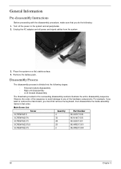
Observe the order of the hardware components. Remove the battery pack. Main Screw List Screw Quantity Part Number SCREW M3*3 4 86.A03V7.006 SCREW M2.5*4 32 86.N1407.003 SCREW M2.0*3 28 86.... proceeding with the disassembly procedure, make sure that order. Unplug the AC adapter and all peripherals. 2. For example, if you want to remove the main board, you must first remove the keyboard, then disassemble the inside assembly frame in that you do the following stages: • External module disassembly • Main unit disassembly...
Observe the order of the hardware components. Remove the battery pack. Main Screw List Screw Quantity Part Number SCREW M3*3 4 86.A03V7.006 SCREW M2.5*4 32 86.N1407.003 SCREW M2.0*3 28 86.... proceeding with the disassembly procedure, make sure that order. Unplug the AC adapter and all peripherals. 2. For example, if you want to remove the main board, you must first remove the keyboard, then disassemble the inside assembly frame in that you do the following stages: • External module disassembly • Main unit disassembly...
Acer Aspire 8940 Service Guide
Page 77
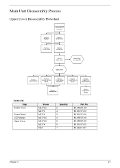
... Disassembly Process Upper Cover Disassembly Flowchart Remove External Modules before proceeding Remove Keyboard Remove Switch Cover Remove Power Board Remove LCD Module Remove Upper Cover Lower Cover (see page 99) Upper Cover Remove Launch Board Remove Volume Control Board Remove Power Saving Board FFC Remove TouchPad Lock Board Remove Finger Print Reader Bracket Remove Media Board Remove Finger Print Reader Screw List Step Switch...
... Disassembly Process Upper Cover Disassembly Flowchart Remove External Modules before proceeding Remove Keyboard Remove Switch Cover Remove Power Board Remove LCD Module Remove Upper Cover Lower Cover (see page 99) Upper Cover Remove Launch Board Remove Volume Control Board Remove Power Saving Board FFC Remove TouchPad Lock Board Remove Finger Print Reader Bracket Remove Media Board Remove Finger Print Reader Screw List Step Switch...
Acer Aspire 8940 Service Guide
Page 79
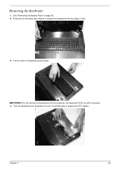
IMPORTANT: Do not remove the Keyboard from the Upper Cover. 3. Removing the Keyboard 1. Turn the Keyboard over and place it on page 52. 2. See "Removing the Battery Pack" on the TouchPad area to release the Keyboard from the computer; the Keyboard FFCs are still connected. 4. Lift the centre of Keyboard up as shown. Chapter 3 69 Press the six securing clips inward to expose the FFC cables.
IMPORTANT: Do not remove the Keyboard from the Upper Cover. 3. Removing the Keyboard 1. Turn the Keyboard over and place it on page 52. 2. See "Removing the Battery Pack" on the TouchPad area to release the Keyboard from the computer; the Keyboard FFCs are still connected. 4. Lift the centre of Keyboard up as shown. Chapter 3 69 Press the six securing clips inward to expose the FFC cables.
Acer Aspire 8940 Service Guide
Page 80
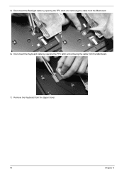
Disconnect the Backlight cable by opening the FFC latch and removing the cable from the Mainboard. 6. Remove the Keyboard from the Mainboard. 7. Disconnect the Keyboard cable by opening the FFC latch and removing the cable from the Upper Cover. 70 Chapter 3 5.
Disconnect the Backlight cable by opening the FFC latch and removing the cable from the Mainboard. 6. Remove the Keyboard from the Mainboard. 7. Disconnect the Keyboard cable by opening the FFC latch and removing the cable from the Upper Cover. 70 Chapter 3 5.
Acer Aspire 8940 Service Guide
Page 82
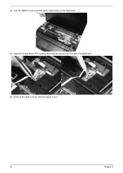
Remove the Switch Cover from the Mainboard. 6. 4. Turn the Switch Cover over and place it face down on the Keyboard. 5. Open the Power Board FFC locking latch and disconnect the FFC from the Upper Cover. 72 Chapter 3
Remove the Switch Cover from the Mainboard. 6. 4. Turn the Switch Cover over and place it face down on the Keyboard. 5. Open the Power Board FFC locking latch and disconnect the FFC from the Upper Cover. 72 Chapter 3
Acer Aspire 8940 Service Guide
Page 278
Kensington Lock Bracket Removing 101, 153 Keyboard Removing 69 Keyboard Failure 196 L Launch Board Removing 81, 171 LCD Bezel Replacing (flush) 140 Replacing (standard) 134 LCD Bezel Cap Removing (flush) 121 Replacing (flush) 142 LCD Brackets Removing (flush) 128 Removing (standard) 118 Replacing (flush) 136 Replacing (standard) 130 LCD Cable Replacing (flush) 136 Replacing (standard) 130 LCD Failure 195...
Kensington Lock Bracket Removing 101, 153 Keyboard Removing 69 Keyboard Failure 196 L Launch Board Removing 81, 171 LCD Bezel Replacing (flush) 140 Replacing (standard) 134 LCD Bezel Cap Removing (flush) 121 Replacing (flush) 142 LCD Brackets Removing (flush) 128 Removing (standard) 118 Replacing (flush) 136 Replacing (standard) 130 LCD Cable Replacing (flush) 136 Replacing (standard) 130 LCD Failure 195...

