Acer Aspire 8940 Service Guide
Page 7
...Basics 11 Using the Keyboard 12 Key Types 12 Windows Keys 13 System Hotkeys 14 Using the System Utilities 15 Acer GridVista (dual-display compatible 15 Hardware Specifications and Configurations 16 System Utilities 31 BIOS Setup Utility 31 Navigating the... Utility 42 Remove HDD/BIOS Password Utilities 43 Machine Disassembly and Replacement 49 Disassembly Requirements 49 General Information 50 Pre-disassembly Instructions 50 Disassembly Process 50 External Module Disassembly Process 51 External Modules Disassembly Flowchart 51 Removing the Battery Pack 52 Removing the ...
...Basics 11 Using the Keyboard 12 Key Types 12 Windows Keys 13 System Hotkeys 14 Using the System Utilities 15 Acer GridVista (dual-display compatible 15 Hardware Specifications and Configurations 16 System Utilities 31 BIOS Setup Utility 31 Navigating the... Utility 42 Remove HDD/BIOS Password Utilities 43 Machine Disassembly and Replacement 49 Disassembly Requirements 49 General Information 50 Pre-disassembly Instructions 50 Disassembly Process 50 External Module Disassembly Process 51 External Modules Disassembly Flowchart 51 Removing the Battery Pack 52 Removing the ...
Acer Aspire 8940 Service Guide
Page 8
... Thermal Module 107 Removing the Graphics Card Heatsink 108 Removing the Graphics Card 109 Removing the CPU 110 LCD Module Disassembly Process 111 Standard Bezel LCD Module Disassembly Flowchart 111 Removing the Standard LCD Bezel 112 Removing the LCD Panel 115 Removing the Camera Board 117 Removing the ...LCD Brackets and FPC Cable 118 Flush Bezel LCD Module Disassembly Flowchart 120 Removing the Flush LCD Bezel Cap 121 Removing the Flush LCD Bezel 123 Removing the LCD Panel 125 Removing the Camera ...
... Thermal Module 107 Removing the Graphics Card Heatsink 108 Removing the Graphics Card 109 Removing the CPU 110 LCD Module Disassembly Process 111 Standard Bezel LCD Module Disassembly Flowchart 111 Removing the Standard LCD Bezel 112 Removing the LCD Panel 115 Removing the Camera Board 117 Removing the ...LCD Brackets and FPC Cable 118 Flush Bezel LCD Module Disassembly Flowchart 120 Removing the Flush LCD Bezel Cap 121 Removing the Flush LCD Bezel 123 Removing the LCD Panel 125 Removing the Camera ...
Acer Aspire 8940 Service Guide
Page 59
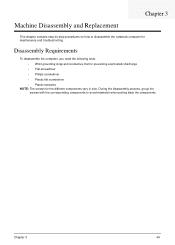
...; Plastic flat screwdriver • Plastic tweezers NOTE: The screws for maintenance and troubleshooting. During the disassembly process, group the screws with the corresponding components to disassemble the notebook computer for the different components vary in size. Machine Disassembly and Replacement Chapter 3 This chapter contains step-by-step procedures on how to avoid mismatch...
...; Plastic flat screwdriver • Plastic tweezers NOTE: The screws for maintenance and troubleshooting. During the disassembly process, group the screws with the corresponding components to disassemble the notebook computer for the different components vary in size. Machine Disassembly and Replacement Chapter 3 This chapter contains step-by-step procedures on how to avoid mismatch...
Acer Aspire 8940 Service Guide
Page 60
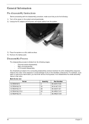
... inside assembly frame in that you do the following stages: • External module disassembly • Main unit disassembly • LCD module disassembly The flowcharts provided in the succeeding disassembly sections illustrate the entire disassembly sequence. Place the system on a flat, stable surface. 4. Unplug the AC adapter and all peripherals. 2. Observe the order of... 32 86.N1407.003 SCREW M2.0*3 28 86.S0207.001 SCREW M2.5*6.5 25 86.ARE07.001 SCREW M2.5*5 2 86.ARE07.004 50 Chapter 3 Disassembly Process The disassembly process is divided into the following : 1.
... inside assembly frame in that you do the following stages: • External module disassembly • Main unit disassembly • LCD module disassembly The flowcharts provided in the succeeding disassembly sections illustrate the entire disassembly sequence. Place the system on a flat, stable surface. 4. Unplug the AC adapter and all peripherals. 2. Observe the order of... 32 86.N1407.003 SCREW M2.0*3 28 86.S0207.001 SCREW M2.5*6.5 25 86.ARE07.001 SCREW M2.5*5 2 86.ARE07.004 50 Chapter 3 Disassembly Process The disassembly process is divided into the following : 1.
Acer Aspire 8940 Service Guide
Page 61
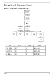
External Module Disassembly Process External Modules Disassembly Flowchart Turn off system and peripherals power Disconnect power and signal cables from system Rem ove Battery Rem ove Dummy Cards Rem ove Lower Door Rem ove ODD Rem ove HDD1 Rem ove HDD2 Rem ove DIMMs Rem ove TV Tuner Screw List Step ODD Module ODD Bracket HDD1 Carrier HDD2 Carrier TV Tuner WLAN Module Screw M2.5*4 M2*3 M3*3 M3*3 M2*3 M2*3 Rem ove WLAN Quantity 1 2 2 2 2 2 Part No. 86.D01V7.001 86.S0207.001 86.A03V7.006 86.A03V7.006 86.S0207.001 86.S0207.001 Chapter 3 51
External Module Disassembly Process External Modules Disassembly Flowchart Turn off system and peripherals power Disconnect power and signal cables from system Rem ove Battery Rem ove Dummy Cards Rem ove Lower Door Rem ove ODD Rem ove HDD1 Rem ove HDD2 Rem ove DIMMs Rem ove TV Tuner Screw List Step ODD Module ODD Bracket HDD1 Carrier HDD2 Carrier TV Tuner WLAN Module Screw M2.5*4 M2*3 M3*3 M3*3 M2*3 M2*3 Rem ove WLAN Quantity 1 2 2 2 2 2 Part No. 86.D01V7.001 86.S0207.001 86.A03V7.006 86.A03V7.006 86.S0207.001 86.S0207.001 Chapter 3 51
Acer Aspire 8940 Service Guide
Page 67
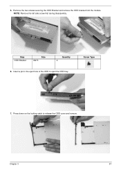
Step ODD Bracket Size M2*3 Quantity 2 6. 5. NOTE: Remove the left side screw first during disassembly. Insert a pin in the eject hole of the ODD to release the ODD cover and remove. Press down on the locking catch to eject the ODD tray. Screw Type 7. Chapter 3 57 Remove the two screws securing the ODD Bracket and remove the ODD bracket from the module.
Step ODD Bracket Size M2*3 Quantity 2 6. 5. NOTE: Remove the left side screw first during disassembly. Insert a pin in the eject hole of the ODD to release the ODD cover and remove. Press down on the locking catch to eject the ODD tray. Screw Type 7. Chapter 3 57 Remove the two screws securing the ODD Bracket and remove the ODD bracket from the module.
Acer Aspire 8940 Service Guide
Page 77
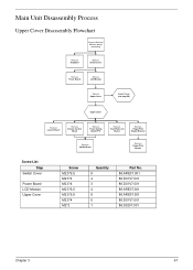
Main Unit Disassembly Process Upper Cover Disassembly Flowchart Remove External Modules before proceeding Remove Keyboard Remove Switch Cover Remove Power Board Remove LCD Module Remove Upper Cover Lower Cover (see page 99) ...
Main Unit Disassembly Process Upper Cover Disassembly Flowchart Remove External Modules before proceeding Remove Keyboard Remove Switch Cover Remove Power Board Remove LCD Module Remove Upper Cover Lower Cover (see page 99) ...
Acer Aspire 8940 Service Guide
Page 78
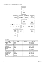
Lower Cover Disassembly Flowchart Remove External Modules before proceeding Rem ove Upper Cover Rem ove RTC Battery Rem ove Bluetooth Module Rem ove USB Board Rem ove Power ...
Lower Cover Disassembly Flowchart Remove External Modules before proceeding Rem ove Upper Cover Rem ove RTC Battery Rem ove Bluetooth Module Rem ove USB Board Rem ove Power ...
Acer Aspire 8940 Service Guide
Page 121
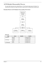
LCD Module Disassembly Process The Aspire 8940 ships with either a Standard Bezel or Flush Bezel with the Standard Bezel detailed below. The following sections detail the two distinct procedures, beginning with glass panel LCD Module. Standard Bezel LCD Module Disassembly Flowchart Remove LCD Panel from Main Unit before proceeding Rem ove LCD Bezel Rem...
LCD Module Disassembly Process The Aspire 8940 ships with either a Standard Bezel or Flush Bezel with the Standard Bezel detailed below. The following sections detail the two distinct procedures, beginning with glass panel LCD Module. Standard Bezel LCD Module Disassembly Flowchart Remove LCD Panel from Main Unit before proceeding Rem ove LCD Bezel Rem...
Acer Aspire 8940 Service Guide
Page 203
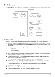
... CD/DVD discs. Connect an external monitor to the computer and switch between the internal display and the external display is still not resolved, see "Disassembly Process" on page 195. 5. No Display Issue If the Display doesn't work, perform the following actions one at a time to correct the problem. 1. If the...
... CD/DVD discs. Connect an external monitor to the computer and switch between the internal display and the external display is still not resolved, see "Disassembly Process" on page 195. 5. No Display Issue If the Display doesn't work, perform the following actions one at a time to correct the problem. 1. If the...
Acer Aspire 8940 Service Guide
Page 204
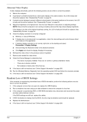
... • No hardware is listed under Other Devices. 9. If the Issue is not normal, right-click on page 50. 4. See "Disassembly Process" on the desktop and select Personalize´ Display Settings. If desktop display resolution is still not resolved, see "Online Support Information"...Reboot the computer. 2. Roll back the video driver to its highest level. Adjust the brightness to the previous version if updated. 7. See "Disassembly Process" on page 265. 10. b. Readjust if necessary. 6. Check the Device Manager to ensure the computer is faulty and should be ...
... • No hardware is listed under Other Devices. 9. If the Issue is not normal, right-click on page 50. 4. See "Disassembly Process" on the desktop and select Personalize´ Display Settings. If desktop display resolution is still not resolved, see "Online Support Information"...Reboot the computer. 2. Roll back the video driver to its highest level. Adjust the brightness to the previous version if updated. 7. See "Disassembly Process" on page 265. 10. b. Readjust if necessary. 6. Check the Device Manager to ensure the computer is faulty and should be ...
Acer Aspire 8940 Service Guide
Page 210
... HDD. b. Click Next. g. For more information see Windows Help and Support. 10. Restore system and file settings from a known good date using up microphone. See "Disassembly Process" on the Boot menu. 6. d. Restart the computer and press F2 to enter the BIOS Utility. Ensure all external devices. 2. Select Set up -to-date...
... HDD. b. Click Next. g. For more information see Windows Help and Support. 10. Restore system and file settings from a known good date using up microphone. See "Disassembly Process" on the Boot menu. 6. d. Restart the computer and press F2 to enter the BIOS Utility. Ensure all external devices. 2. Select Set up -to-date...

Acer Aspire 8940 Service Guide
Page 277
...) 130 Common Problems 192 CPU 110 Replacing 144 D DIMM Modules Removing 62 Display 4 E Express Dummy Card Removing 53 External Module Disassembly Flowchart 51 Index F Features 1 Flash Utility 39 Flush Bezel Disassembly Flowchart 120 Flush LCD Bezel Removing 123 FP Reader Bracket Removing 89, 164 FPC Cable Removing (flush) 128 Removing (standard) 118...
...) 130 Common Problems 192 CPU 110 Replacing 144 D DIMM Modules Removing 62 Display 4 E Express Dummy Card Removing 53 External Module Disassembly Flowchart 51 Index F Features 1 Flash Utility 39 Flush Bezel Disassembly Flowchart 120 Flush LCD Bezel Removing 123 FP Reader Bracket Removing 89, 164 FPC Cable Removing (flush) 128 Removing (standard) 118...
Acer Aspire 8940 Service Guide
Page 278
...standard) 118 Replacing (flush) 136 Replacing (standard) 130 LCD Cable Replacing (flush) 136 Replacing (standard) 130 LCD Failure 195 LCD Module Disassembly 111 Removing 74 LCD Module Reassembly Procedure 130 LCD Panel Removing (flush) 125 Removing (standard) 115 Replacing (flush) 136 Replacing (standard)... 130 Left Hinge Support Removing 105, 149 Lower Cover Disassembly Flowchart 68 Lower Covers Removing 55 M Main Module Reassembly Procedure 144 Main Unit Disassembly Flowchart 67 Mainboard Removing 99, 154 268 Replacing 153 Media Board Removing 85, 167 Memory...
...standard) 118 Replacing (flush) 136 Replacing (standard) 130 LCD Cable Replacing (flush) 136 Replacing (standard) 130 LCD Failure 195 LCD Module Disassembly 111 Removing 74 LCD Module Reassembly Procedure 130 LCD Panel Removing (flush) 125 Removing (standard) 115 Replacing (flush) 136 Replacing (standard)... 130 Left Hinge Support Removing 105, 149 Lower Cover Disassembly Flowchart 68 Lower Covers Removing 55 M Main Module Reassembly Procedure 144 Main Unit Disassembly Flowchart 67 Mainboard Removing 99, 154 268 Replacing 153 Media Board Removing 85, 167 Memory...
Acer Aspire 8940 Service Guide
Page 279
Speaker Module Removing 106, 148 Standard Bezel Disassembly Flowchart 111 Standard LCD Bezel Removing 112 Subwoofer Removing 103, 150 Switch Cover Removing 71, 180 System Block Diagram 4 T Test Compatible Components 239 Thermal Grease ... On 192 TouchPad 197 TV Tuner Antenna Removing 102, 152 TV Tuner Module Removing 63, 185 U Undetermined Problems 202 Upper Cover Removing 77 Upper Cover Disassembly Flowchart 67 USB Board Removing 96, 156 utility BIOS 31-39 V Volume Control Board Removing 82, 169 W Windows 2000 Environment Test 240 WLAN Board 65...
Speaker Module Removing 106, 148 Standard Bezel Disassembly Flowchart 111 Standard LCD Bezel Removing 112 Subwoofer Removing 103, 150 Switch Cover Removing 71, 180 System Block Diagram 4 T Test Compatible Components 239 Thermal Grease ... On 192 TouchPad 197 TV Tuner Antenna Removing 102, 152 TV Tuner Module Removing 63, 185 U Undetermined Problems 202 Upper Cover Removing 77 Upper Cover Disassembly Flowchart 67 USB Board Removing 96, 156 utility BIOS 31-39 V Volume Control Board Removing 82, 169 W Windows 2000 Environment Test 240 WLAN Board 65...


