

Service Guide
Page 2
..., group the screws with the corresponding components to disassemble the notebook computer for the different components vary in size. Disassembly Requirements To disassemble the computer, you need the following tools: • Wrist grounding strap and conductive mat for preventing electrostatic...; Hex screwdriver • Plastic flat screwdriver • Plastic tweezers NOTE: The screws for maintenance and troubleshooting. Machine Disassembly and Replacement Chapter 3 This chapter contains step-by-step procedures on how to avoid mismatch when putting back the components. Chapter 3 ...
..., group the screws with the corresponding components to disassemble the notebook computer for the different components vary in size. Disassembly Requirements To disassemble the computer, you need the following tools: • Wrist grounding strap and conductive mat for preventing electrostatic...; Hex screwdriver • Plastic flat screwdriver • Plastic tweezers NOTE: The screws for maintenance and troubleshooting. Machine Disassembly and Replacement Chapter 3 This chapter contains step-by-step procedures on how to avoid mismatch when putting back the components. Chapter 3 ...
Service Guide
Page 3
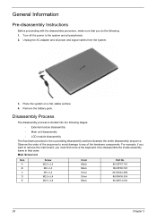
... main board, you do the following: 1. Observe the order of the hardware components. Place the system on a flat, stable surface. 4. Disassembly Process The disassembly process is divided into the following stages: • External module disassembly • Main unit disassembly • LCD module disassembly The flowcharts provided in that you must first remove the keyboard, then...
... main board, you do the following: 1. Observe the order of the hardware components. Place the system on a flat, stable surface. 4. Disassembly Process The disassembly process is divided into the following stages: • External module disassembly • Main unit disassembly • LCD module disassembly The flowcharts provided in that you must first remove the keyboard, then...
Service Guide
Page 4
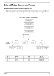
For example, if you want to remove the main board, you on the components that order. Item B C E Screw M2 x L3 M3 x L4 M2.5 x L6 Color Black Silver Black Part No. 86.00F80.723 86.9A524.4R0 86.00E12.536 Chapter 3 29 External Module Disassembly Process External Modules Disassembly Flowchart The flowchart below gives you a graphic representation on the entire disassembly sequence and instructs you must first remove the keyboard, then disassemble the inside assembly frame in that need to be removed during servicing.
For example, if you want to remove the main board, you on the components that order. Item B C E Screw M2 x L3 M3 x L4 M2.5 x L6 Color Black Silver Black Part No. 86.00F80.723 86.9A524.4R0 86.00E12.536 Chapter 3 29 External Module Disassembly Process External Modules Disassembly Flowchart The flowchart below gives you a graphic representation on the entire disassembly sequence and instructs you must first remove the keyboard, then disassemble the inside assembly frame in that need to be removed during servicing.


