Acer Aspire 7736, Aspire 7736Z Notebook Series Start Guide
Page 3
... get started with language such as the AcerSystem User Guide mentioned below will run the Adobe Reader setup program first. The Aspire Series Generic User Guide contains useful information applying to use your computer. Please understand that due to the basic features and ... needs. Your guides To help you for making an Acer notebook your choice for your computer, clicking on your new computer. Such instances are only contained in the Aspire product series. It covers basic topics such as system utilities, data recovery, expansion options and troubleshooting.
... get started with language such as the AcerSystem User Guide mentioned below will run the Adobe Reader setup program first. The Aspire Series Generic User Guide contains useful information applying to use your computer. Please understand that due to the basic features and ... needs. Your guides To help you for making an Acer notebook your choice for your computer, clicking on your new computer. Such instances are only contained in the Aspire product series. It covers basic topics such as system utilities, data recovery, expansion options and troubleshooting.
Service Guide
Page 8
... Locations 103 Main Board 103 Clearing Password Check and BIOS Recovery 105 Clearing Password Check 105 BIOS Recovery by Crisis Disk 107 FRU (Field Replaceable Unit) List 111 Aspire 7736/7736Z/7336 Series and Aspire 7540 Series Exploded Diagram . . . . .112 Model Definition and Configuration 143 Aspire 7736/7736Z/7336 Series 144 Test Compatible Components 171...
... Locations 103 Main Board 103 Clearing Password Check and BIOS Recovery 105 Clearing Password Check 105 BIOS Recovery by Crisis Disk 107 FRU (Field Replaceable Unit) List 111 Aspire 7736/7736Z/7336 Series and Aspire 7540 Series Exploded Diagram . . . . .112 Model Definition and Configuration 143 Aspire 7736/7736Z/7336 Series 144 Test Compatible Components 171...
Service Guide
Page 39
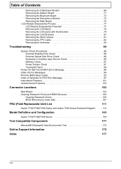
...Boot Menu: D2D Recovery: SATAMode [Enabled] [Enabled] [Disabled] [Enabled] [AHCI Mode] F1 Help Esc Exit Select Item -/+ Change Values F9 Setup Defaults Select Menu Enter Select Sub-Menu F10 Save and Exit NOTE: The screen above is for your reference only. Chapter 2 31 Aspire 7736/7736Z/7336 ...KB 957 MB 64 MB Item Specific Help , , or selects field. Actual values may differ. Quiet Boot: Network Boot: F12 Boot Menu: D2D Recovery: SATAMode [Enabled] [Enabled] [Disabled] [Enabled] [AHCI] F1 Help Esc Exit Select Item -/+ Change Values F9 Setup Defaults Select Menu Enter Select ...
...Boot Menu: D2D Recovery: SATAMode [Enabled] [Enabled] [Disabled] [Enabled] [AHCI Mode] F1 Help Esc Exit Select Item -/+ Change Values F9 Setup Defaults Select Menu Enter Select Sub-Menu F10 Save and Exit NOTE: The screen above is for your reference only. Chapter 2 31 Aspire 7736/7736Z/7336 ...KB 957 MB 64 MB Item Specific Help , , or selects field. Actual values may differ. Quiet Boot: Network Boot: F12 Boot Menu: D2D Recovery: SATAMode [Enabled] [Enabled] [Disabled] [Enabled] [AHCI] F1 Help Esc Exit Select Item -/+ Change Values F9 Setup Defaults Select Menu Enter Select ...
Service Guide
Page 40
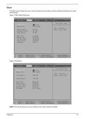
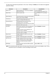
... Date System Memory Total Memory Extended Memory VGA Memory Quiet Boot Network Boot F12 Boot Menu D2D Recovery SATA Mode Description Sets the system time. This field reports the memory size of the system. For Aspire 8530 Series only. Disabled: Customer Logo is not displayed, and Summary Screen is disabled or enabled...
... Date System Memory Total Memory Extended Memory VGA Memory Quiet Boot Network Boot F12 Boot Menu D2D Recovery SATA Mode Description Sets the system time. This field reports the memory size of the system. For Aspire 8530 Series only. Disabled: Customer Logo is not displayed, and Summary Screen is disabled or enabled...
Service Guide
Page 47
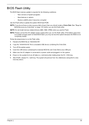
... + ESC key. 7. After POST, release Fn + ESC key. The system should create a Crisis Disk (See "Steps for BIOS Recovery by Crisis Disk" on the system from the USB device and perform crisis recovery action. Follow the steps below to a bootable USB device containing the Crisis Disk. 3. Copy the "XXXXXXX.FD" file to...) when you run the Flash utility: 1. BIOS Flash Utility The BIOS flash memory update is not completely loaded. NOTE: If you do not have a crisis recovery disk at hand, then you should boot from an off the system power. 4. Turn off state (i.e.
... + ESC key. 7. After POST, release Fn + ESC key. The system should create a Crisis Disk (See "Steps for BIOS Recovery by Crisis Disk" on the system from the USB device and perform crisis recovery action. Follow the steps below to a bootable USB device containing the Crisis Disk. 3. Copy the "XXXXXXX.FD" file to...) when you run the Flash utility: 1. BIOS Flash Utility The BIOS flash memory update is not completely loaded. NOTE: If you do not have a crisis recovery disk at hand, then you should boot from an off the system power. 4. Turn off state (i.e.
Service Guide
Page 102
... Setup System Management Mode (SMM) area Display external L2 cache size Load custom defaults (optional) Display shadow-area message Display possible high address for UMB recovery Display error messages Check for configuration errors Check for keyboard errors Set up hardware interrupt vectors Initialize coprocessor if present Disable onboard Super I/O ports and...
... Setup System Management Mode (SMM) area Display external L2 cache size Load custom defaults (optional) Display shadow-area message Display possible high address for UMB recovery Display error messages Check for configuration errors Check for keyboard errors Set up hardware interrupt vectors Initialize coprocessor if present Disable onboard Super I/O ports and...

Service Guide
Page 104
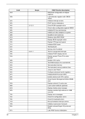
... Force check (optional) Extended checksum (optional) Unknown interrupt Initialize the chipset Initialize the bridge Initialize the CPU Initialize the system timer Initialize system I/O Check force recovery boot Checksum BIOS ROM Go to BIOS Set Huge Segment Initialize Multi Processor Initialize OEM special code Initialize PIC and DMA Initialize Memory type Initialize...
... Force check (optional) Extended checksum (optional) Unknown interrupt Initialize the chipset Initialize the bridge Initialize the CPU Initialize the system timer Initialize system I/O Check force recovery boot Checksum BIOS ROM Go to BIOS Set Huge Segment Initialize Multi Processor Initialize OEM special code Initialize PIC and DMA Initialize Memory type Initialize...
Service Guide
Page 113
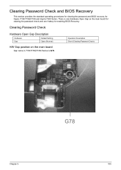
Clearing Password Check Hardware Open Gap Description Hardware Gap Default Setting Open (Normal) HW Gap position on the main board for clearing the password check and one Hotkey for Aspire 7736/7736Z/7336 and Aspire 7540 Series. There is one Hardware Open Gap on the main board: Gap name in 7736/7736Z/7336 Series is G78. Clearing Password Check and BIOS Recovery This section provides the standard operating procedures for clearing the password and BIOS recovery for enabling BIOS Recovery. Operation Description Short (Clearing Password Check) Chapter 5 G78 105
Clearing Password Check Hardware Open Gap Description Hardware Gap Default Setting Open (Normal) HW Gap position on the main board for clearing the password check and one Hotkey for Aspire 7736/7736Z/7336 and Aspire 7540 Series. There is one Hardware Open Gap on the main board: Gap name in 7736/7736Z/7336 Series is G78. Clearing Password Check and BIOS Recovery This section provides the standard operating procedures for clearing the password and BIOS recovery for enabling BIOS Recovery. Operation Description Short (Clearing Password Check) Chapter 5 G78 105

Service Guide
Page 115
...can enable this function is used to the BIOS flash failed system. 3. Set up the system with minimum BIOS initialization. Chapter 5 107 BIOS Recovery by Crisis Disk Before doing this, prepare a Crisis Disk (refer to the "Steps for Creating the Crisis Disk in Windows XP/Vista" section... USB storage device containing the Crisis Disk to a USB port connected to boot up another computer loaded with the Crisis BIOS Recovery process. 4. After the Crisis Recovery process is finished, the system will force the BIOS to a successful one once the previous BIOS flashing process failed. Note ...
...can enable this function is used to the BIOS flash failed system. 3. Set up the system with minimum BIOS initialization. Chapter 5 107 BIOS Recovery by Crisis Disk Before doing this, prepare a Crisis Disk (refer to the "Steps for Creating the Crisis Disk in Windows XP/Vista" section... USB storage device containing the Crisis Disk to a USB port connected to boot up another computer loaded with the Crisis BIOS Recovery process. 4. After the Crisis Recovery process is finished, the system will force the BIOS to a successful one once the previous BIOS flashing process failed. Note ...
Service Guide
Page 185
... removing 45 BIOS 19 vendor 19 Version 19 BIOS Recovery 105 BIOS Recovery Boot Block 107 BIOS Recovery by Crisis Disk 107 steps 107 BIOS Recovery Hotkey 107 BIOS Utility 27-39 Navigating 28 System Security 38 block diagram Aspire 7540 Series 5 Aspire 7738/7738G Series and 7735/7735G/ 7735Z/7735ZG Series... BIOS Password steps 106 Clearing Password 105 computer on indicator 7 CPU removing 54 CPU Fan True Value Table 19 Crisis Disk creating 107 Crisis Recovery Disk 39 D DIMM module removing 51 E Environment Test 172 Euro 15 External CD-ROM Drive Check 86 External Module Disassembly Flowchart 43 F...
... removing 45 BIOS 19 vendor 19 Version 19 BIOS Recovery 105 BIOS Recovery Boot Block 107 BIOS Recovery by Crisis Disk 107 steps 107 BIOS Recovery Hotkey 107 BIOS Utility 27-39 Navigating 28 System Security 38 block diagram Aspire 7540 Series 5 Aspire 7738/7738G Series and 7735/7735G/ 7735Z/7735ZG Series... BIOS Password steps 106 Clearing Password 105 computer on indicator 7 CPU removing 54 CPU Fan True Value Table 19 Crisis Disk creating 107 Crisis Recovery Disk 39 D DIMM module removing 51 E Environment Test 172 Euro 15 External CD-ROM Drive Check 86 External Module Disassembly Flowchart 43 F...


