

Aspire 7720 / 7720G Service Guide
Page 42
...to 264V AC, 47Hz to 63Hz 1.7A 220A@115VAC 220A@230VAC 82% min. @115VAC input full load System Power Management ACPI mode Mech. LCD 17" inch Item Display Mode Typical White Luminance (cd/m2) also called Brightness Luminance Uniformity Contrast Ratio Response Time (Optical Rise Time/Fall ... Normally White 300 70 250 8 3.3V N/A 600 317.3x242.0x6. 5 1 channel LVDS 262,144 40/40 20/40 0 to +50 -20 to +60 LCD Inverter Item Vendor & model name Brightness conditions Input voltage (V) Input current (mA) Output voltage (V, rms) Output current (mA, rms) Output voltage frequency (k Hz) Specification ...
...to 264V AC, 47Hz to 63Hz 1.7A 220A@115VAC 220A@230VAC 82% min. @115VAC input full load System Power Management ACPI mode Mech. LCD 17" inch Item Display Mode Typical White Luminance (cd/m2) also called Brightness Luminance Uniformity Contrast Ratio Response Time (Optical Rise Time/Fall ... Normally White 300 70 250 8 3.3V N/A 600 317.3x242.0x6. 5 1 channel LVDS 262,144 40/40 20/40 0 to +50 -20 to +60 LCD Inverter Item Vendor & model name Brightness conditions Input voltage (V) Input current (mA) Output voltage (V, rms) Output current (mA, rms) Output voltage frequency (k Hz) Specification ...

Aspire 7720 / 7720G Service Guide
Page 74
...two screws fastening the CCD board to the LCD panel. 5. Remove the two screws fastening the CCD module to the LCD panel and remove the CCD module. 8. Then remove the four screws fastening the LCD bezel. 3. Detach the LCD bezel from the inverter board. 6. Detach the CCD cable connector ...from the LCD panel as shown. 2. Disassembling the LCD Module 1. Remove the four screw ...
...two screws fastening the CCD board to the LCD panel. 5. Remove the two screws fastening the CCD module to the LCD panel and remove the CCD module. 8. Then remove the four screws fastening the LCD bezel. 3. Detach the LCD bezel from the inverter board. 6. Detach the CCD cable connector ...from the LCD panel as shown. 2. Disassembling the LCD Module 1. Remove the four screw ...

Aspire 7720 / 7720G Service Guide
Page 85
... pack and power adapter). But you can see POST on and LCD is blank. Power source (battery pack and power adapter). Reconnect the DIMM. Reconnect the LCD connector Hard disk drive LCD inverter ID LCD cable LCD Inverter LCD System board No beep, power-on indicator turns on an external ... 4 79 LED board. System board. See "Power System Check" on and LCD is blank. LCD inverter ID LCD cable LCD inverter LCD System board No beep, power-on indicator turns on and a blinking cursor shown on LCD during POST but system runs correctly. System board No beep during POST.
... pack and power adapter). But you can see POST on and LCD is blank. Power source (battery pack and power adapter). Reconnect the DIMM. Reconnect the LCD connector Hard disk drive LCD inverter ID LCD cable LCD Inverter LCD System board No beep, power-on indicator turns on an external ... 4 79 LED board. System board. See "Power System Check" on and LCD is blank. LCD inverter ID LCD cable LCD inverter LCD System board No beep, power-on indicator turns on and a blinking cursor shown on LCD during POST but system runs correctly. System board No beep during POST.
Aspire 7720 / 7720G Service Guide
Page 90
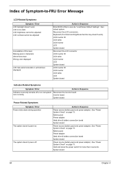
LCD inverter ID LCD cable LCD inverter LCD System board Reconnect the LCD connector LCD inverter ID LCD cable LCD inverter LCD System board LCD inverter ID LCD inverter LCD cable LCD System board Indicator-Related Symptoms Symptom / Error Action in Sequence Enter BIOS Utility to -FRU Error Message LCD-Related Symptoms Symptom / Error LCD backlight doesn't work ). See "Power System Check" on page 73. Hold and press the power switch for...
LCD inverter ID LCD cable LCD inverter LCD System board Reconnect the LCD connector LCD inverter ID LCD cable LCD inverter LCD System board LCD inverter ID LCD inverter LCD cable LCD System board Indicator-Related Symptoms Symptom / Error Action in Sequence Enter BIOS Utility to -FRU Error Message LCD-Related Symptoms Symptom / Error LCD backlight doesn't work ). See "Power System Check" on page 73. Hold and press the power switch for...


