
Aspire 7720 / 7720G Service Guide
Page 36
... Cache size 1st level cache control 2st level cache control Cache scheme control Built-in CPU 2MB Always enabled Always enabled Fixed in write-back Specification 30 Chapter 1 After that, power off the system and remove the HDD. Then you need to check PXE version, press F2 to enter BIOS ... 800 MHz FSB) or higher Intel® 965PM/965GM Express chipset+ICH8M Intel socket 1466pin FCBGA 0.944~1.3V CPU Fan True Value Table CPU Temperature Core 0 86 88 91 95 TEST Condition: 35W@Ambient 35 degree C Fan Speed Core 1 (rpm) 86 3700 88 3450 91 3150 95 2800 Acoustic Level (dBA) 39 36.5 ...
... Cache size 1st level cache control 2st level cache control Cache scheme control Built-in CPU 2MB Always enabled Always enabled Fixed in write-back Specification 30 Chapter 1 After that, power off the system and remove the HDD. Then you need to check PXE version, press F2 to enter BIOS ... 800 MHz FSB) or higher Intel® 965PM/965GM Express chipset+ICH8M Intel socket 1466pin FCBGA 0.944~1.3V CPU Fan True Value Table CPU Temperature Core 0 86 88 91 95 TEST Condition: 35W@Ambient 35 degree C Fan Speed Core 1 (rpm) 86 3700 88 3450 91 3150 95 2800 Acoustic Level (dBA) 39 36.5 ...

Aspire 7720 / 7720G Service Guide
Page 61
For example, if you want to remove the system board, you on the components that order. Start Battery Pack B*1 D*1 System Fan B*4 Thermal Module F*1 ODD Module CPU D*5 F*1 Thermal Door Memory Lower Case Assembly F*1 Mimi Cover F*2 HDD Door H*4 HDD Bracket HDD Middle Cover F*2 Keyboard C*2 LCD hinges to logic D*2 LCD hinges to ... Disassembly Procedure Flowchart The flowchart on the succeeding page gives you a graphic representation on the entire disassembly sequence and instructs you must first remove the keyboard, then disassemble the inside assembly frame in that need to be...
For example, if you want to remove the system board, you on the components that order. Start Battery Pack B*1 D*1 System Fan B*4 Thermal Module F*1 ODD Module CPU D*5 F*1 Thermal Door Memory Lower Case Assembly F*1 Mimi Cover F*2 HDD Door H*4 HDD Bracket HDD Middle Cover F*2 Keyboard C*2 LCD hinges to logic D*2 LCD hinges to ... Disassembly Procedure Flowchart The flowchart on the succeeding page gives you a graphic representation on the entire disassembly sequence and instructs you must first remove the keyboard, then disassemble the inside assembly frame in that need to be...
Aspire 7720 / 7720G Service Guide
Page 64
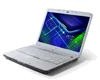
... module. 4. Pop out the memory from the main unit. 3. Removing the HDD Module/Memory/Wireless LAN Card/Modem Card/ TV Tuner Card/System Fan/Thermal Modules/VGA Board/CPU/ Keyboard and the LCD Module Removing the HDD Module 1. Remove the four screws holding the thermal cover. 2. Remove the two screws fastening the HDD cover. 2. Detach the...
... module. 4. Pop out the memory from the main unit. 3. Removing the HDD Module/Memory/Wireless LAN Card/Modem Card/ TV Tuner Card/System Fan/Thermal Modules/VGA Board/CPU/ Keyboard and the LCD Module Removing the HDD Module 1. Remove the four screws holding the thermal cover. 2. Remove the two screws fastening the HDD cover. 2. Detach the...
Aspire 7720 / 7720G Service Guide
Page 66
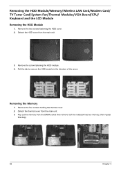
... VGA thermal module as shown. 5. Disconnect the fan cable from the CPU socket carefully. Remove the four spring screws holding the CPU thermal module. 4. Remove the four spring screws holding the VGA thermal module. 6. Remove the CPU from the main board. 2. Remove the three screws holding the system fan. 3. Then detach the CPU thermal module as shown. 7. NOTE: VGA thermal...
... VGA thermal module as shown. 5. Disconnect the fan cable from the CPU socket carefully. Remove the four spring screws holding the CPU thermal module. 4. Remove the four spring screws holding the VGA thermal module. 6. Remove the CPU from the main board. 2. Remove the three screws holding the system fan. 3. Then detach the CPU thermal module as shown. 7. NOTE: VGA thermal...


