
Acer Aspire 7535 Notebook Service Guide
Page 7
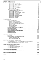
...Acer GridVista (dual-display compatible 18 Hardware Specifications and Configurations 19 System Utilities 27 BIOS Setup Utility 27 Navigating the BIOS Utility 28 Information 29 Main 31 Security 33 Boot 37 Exit 38 BIOS Flash Utility 39 Remove HDD Password 40 Machine Disassembly and Replacement 41 Disassembly... Requirements 41 General Information 42 Pre-disassembly Instructions 42 Disassembly Process 42 External Module Disassembly Process 43 External Modules Disassembly Flowchart 43 Removing the ...
...Acer GridVista (dual-display compatible 18 Hardware Specifications and Configurations 19 System Utilities 27 BIOS Setup Utility 27 Navigating the BIOS Utility 28 Information 29 Main 31 Security 33 Boot 37 Exit 38 BIOS Flash Utility 39 Remove HDD Password 40 Machine Disassembly and Replacement 41 Disassembly... Requirements 41 General Information 42 Pre-disassembly Instructions 42 Disassembly Process 42 External Module Disassembly Process 43 External Modules Disassembly Flowchart 43 Removing the ...
Acer Aspire 7535 Notebook Service Guide
Page 8
... Modem Module 74 Removing the Main Board 75 Removing the Heatsink Module 78 Removing the CPU 82 LCD Module Disassembly Process 84 LCD Module Disassembly Flowchart 84 Removing the LCD Bezel 85 Removing the LCD panel with the Brackets 88 Removing the LCD Brackets...FRU (Field Replaceable Unit) List 121 Aspire 7738/7738G Series, Aspire7735/7735G/7735Z/7735ZG Series and Aspire 7535/7535G/7235 Series Exploded Diagram 122 Model Definition and Configuration 183 Aspire 7738/7738G Series 184 Aspire 7735/7735G/7735Z/7735ZG Series 193 Aspire 7535/7535G/7235 Series 198 Test Compatible ...
... Modem Module 74 Removing the Main Board 75 Removing the Heatsink Module 78 Removing the CPU 82 LCD Module Disassembly Process 84 LCD Module Disassembly Flowchart 84 Removing the LCD Bezel 85 Removing the LCD panel with the Brackets 88 Removing the LCD Brackets...FRU (Field Replaceable Unit) List 121 Aspire 7738/7738G Series, Aspire7735/7735G/7735Z/7735ZG Series and Aspire 7535/7535G/7235 Series Exploded Diagram 122 Model Definition and Configuration 183 Aspire 7738/7738G Series 184 Aspire 7735/7735G/7735Z/7735ZG Series 193 Aspire 7535/7535G/7235 Series 198 Test Compatible ...

Acer Aspire 7535 Notebook Service Guide
Page 49
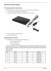
... Replacement This chapter contains step-by-step procedures on how to avoid mismatch when putting back the components. Disassembly Requirements To disassemble the computer, you need the following tools: • Wrist grounding strap and conductive mat for preventing electrostatic discharge • Flat screwdriver • Philips screwdriver • ...
... Replacement This chapter contains step-by-step procedures on how to avoid mismatch when putting back the components. Disassembly Requirements To disassemble the computer, you need the following tools: • Wrist grounding strap and conductive mat for preventing electrostatic discharge • Flat screwdriver • Philips screwdriver • ...
Acer Aspire 7535 Notebook Service Guide
Page 50
... from the system. 3. Unplug the AC adapter and all peripherals. 2. Disassembly Process The disassembly process is divided into the following stages: • External module disassembly • Main unit disassembly • LCD module disassembly The flowcharts provided in that you must first remove the keyboard, then....00F87.735 86.9A552.4R0 86.00H06.622 86.9A553.7R0 86.00G58.725 42 Chapter 3 General Information Pre-disassembly Instructions Before proceeding with the disassembly procedure, make sure that order. Place the system on a flat, stable surface. 4. Observe the order of ...
... from the system. 3. Unplug the AC adapter and all peripherals. 2. Disassembly Process The disassembly process is divided into the following stages: • External module disassembly • Main unit disassembly • LCD module disassembly The flowcharts provided in that you must first remove the keyboard, then....00F87.735 86.9A552.4R0 86.00H06.622 86.9A553.7R0 86.00G58.725 42 Chapter 3 General Information Pre-disassembly Instructions Before proceeding with the disassembly procedure, make sure that order. Place the system on a flat, stable surface. 4. Observe the order of ...
Acer Aspire 7535 Notebook Service Guide
Page 51
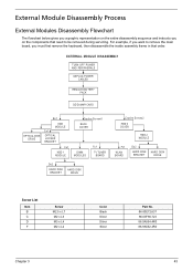
For example, if you must first remove the keyboard, then disassemble the inside assembly frame in that order. EXTERNAL MODULE DISASSEMBLY TURN OFF POWER AND PERIPHERALS UNPLUG POWER CABLES REMOVE BATTERY PACK SD DUMMY CARD OPTICAL DISK DRIVE Bx1 ODD MODULE Cx1 OPTICAL .... 86.00E72.637 86.00F80.723 86.9A554.4R0 86.9A552.4R0 Chapter 3 43 External Module Disassembly Process External Modules Disassembly Flowchart The flowchart below gives you a graphic representation on the entire disassembly sequence and instructs you on the components that need to remove the main board, you want to ...
For example, if you must first remove the keyboard, then disassemble the inside assembly frame in that order. EXTERNAL MODULE DISASSEMBLY TURN OFF POWER AND PERIPHERALS UNPLUG POWER CABLES REMOVE BATTERY PACK SD DUMMY CARD OPTICAL DISK DRIVE Bx1 ODD MODULE Cx1 OPTICAL .... 86.00E72.637 86.00F80.723 86.9A554.4R0 86.9A552.4R0 Chapter 3 43 External Module Disassembly Process External Modules Disassembly Flowchart The flowchart below gives you a graphic representation on the entire disassembly sequence and instructs you on the components that need to remove the main board, you want to ...
Acer Aspire 7535 Notebook Service Guide
Page 64
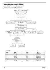
Main Unit Disassembly Process Main Unit Disassembly Flowchart MAIN UNIT DISASSEMBLY MAIN UNIT B x 15 F x 1 LOWER CASE MIDDLE COVER F x 2 POWER BUTTON BOARD KEYBOARD Ex4 LCD MODULE F x 2 POWER SAVING BOARD I x 2 F x 3 UPPER CASE F x 4 F x 2 MODEM CARD C x 2 LAUNCH BOARD F x 1 USB MODULE ...
Main Unit Disassembly Process Main Unit Disassembly Flowchart MAIN UNIT DISASSEMBLY MAIN UNIT B x 15 F x 1 LOWER CASE MIDDLE COVER F x 2 POWER BUTTON BOARD KEYBOARD Ex4 LCD MODULE F x 2 POWER SAVING BOARD I x 2 F x 3 UPPER CASE F x 4 F x 2 MODEM CARD C x 2 LAUNCH BOARD F x 1 USB MODULE ...

Acer Aspire 7535 Notebook Service Guide
Page 90
...See "Removing the Hard Disk Drive 1 (HDD1) Module" on page 72. 17. See "Removing the USB Board Module" on page 48. 6. See "LCD Module Disassembly Process" on page 48. 5. See "Removing the Back Cover" on page 84. 20. See "Removing the DIMM Module" on page 64. 14. See "Separating... turn the CPU socket latch counter-clockwise to release the CPU. 82 Chapter 3 Removing the CPU NOTE: Aspire 7738/7738G and Aspire 7735/7735G/7735Z/7735ZG Series uses the Intel® processor, while Aspire 7535/7535G/7235 Series uses the AMD® processor. See "Removing the SD Dummy Card" on page 60...
...See "Removing the Hard Disk Drive 1 (HDD1) Module" on page 72. 17. See "Removing the USB Board Module" on page 48. 6. See "LCD Module Disassembly Process" on page 48. 5. See "Removing the Back Cover" on page 84. 20. See "Removing the DIMM Module" on page 64. 14. See "Separating... turn the CPU socket latch counter-clockwise to release the CPU. 82 Chapter 3 Removing the CPU NOTE: Aspire 7738/7738G and Aspire 7735/7735G/7735Z/7735ZG Series uses the Intel® processor, while Aspire 7535/7535G/7235 Series uses the AMD® processor. See "Removing the SD Dummy Card" on page 60...
Acer Aspire 7535 Notebook Service Guide
Page 219
... BIOS Recovery by Crisis Disk 117 steps 117 BIOS Recovery Hotkey 117 BIOS Utility 27-39 Navigating 28 System Security 38 block diagram Aspire 7535/7535G/7235 Series 5 Aspire 7738/7738G Series and 7735/7735G/ 7735Z/7735ZG Series 4 button/indicator Bluetooth 7, 11 Wireless LAN 7, 11 buttons easy-launch 11... creating 117 Crisis Recovery Disk 39 D DIMM module removing 53 E Environment Test 206 Euro 15 External CD-ROM Drive Check 96 External Module Disassembly Flowchart 43 F Fingerprint/button and touchpad boards removing 68 Flash Utility 39 FRU (Field Replaceable Unit) List 121 H Hard disk 21 HDD...
... BIOS Recovery by Crisis Disk 117 steps 117 BIOS Recovery Hotkey 117 BIOS Utility 27-39 Navigating 28 System Security 38 block diagram Aspire 7535/7535G/7235 Series 5 Aspire 7738/7738G Series and 7735/7735G/ 7735Z/7735ZG Series 4 button/indicator Bluetooth 7, 11 Wireless LAN 7, 11 buttons easy-launch 11... creating 117 Crisis Recovery Disk 39 D DIMM module removing 53 E Environment Test 206 Euro 15 External CD-ROM Drive Check 96 External Module Disassembly Flowchart 43 F Fingerprint/button and touchpad boards removing 68 Flash Utility 39 FRU (Field Replaceable Unit) List 121 H Hard disk 21 HDD...
Acer Aspire 7535 Notebook Service Guide
Page 220
...Acer PowerSmart 7 Backup 7, 11 US dollar 15 Keyboard 7, 13, 25 removing 60 Keyboard or Auxiliary Input Device Check 96 L Launch board removing 70 LCD bezel removing 85 LCD Brackets removing 90 LCD Module Disassembly Flowchart 84 LCD with the brackets removing 88 Locations connectors 113 M Main Screw List 42 Main Unit Disassembly...42 Speakers 7 System 4 Block Diagram 4 System Check Procedures 96 System Memory 19 System Utilities 17, 27 System utilities Acer GridVista 18 T Test Compatible Components 205 Touchpad 7 touchpad using 11 Touchpad Check 98 Troubleshooting 95 U Undetermined Problems 112 ...
...Acer PowerSmart 7 Backup 7, 11 US dollar 15 Keyboard 7, 13, 25 removing 60 Keyboard or Auxiliary Input Device Check 96 L Launch board removing 70 LCD bezel removing 85 LCD Brackets removing 90 LCD Module Disassembly Flowchart 84 LCD with the brackets removing 88 Locations connectors 113 M Main Screw List 42 Main Unit Disassembly...42 Speakers 7 System 4 Block Diagram 4 System Check Procedures 96 System Memory 19 System Utilities 17, 27 System utilities Acer GridVista 18 T Test Compatible Components 205 Touchpad 7 touchpad using 11 Touchpad Check 98 Troubleshooting 95 U Undetermined Problems 112 ...


