Aspire 7230/7530/7530G Service Guide
Page 7
...Keys and embedded numeric keypad 12 Windows Keys 13 Hot Keys 14 Special Key 15 Using the System Utilities 16 Acer GridVista (dual-display compatible 16 Hardware Specifications and Configurations 18 System Utilities 29 BIOS Setup Utility 29 Navigating the ... BIOS Flash Utility 41 Remove HDD/BIOS Utility 42 Machine Disassembly and Replacement 45 Disassembly Requirements 45 General Information 46 Pre-disassembly Instructions 46 Disassembly Process 46 External Module Disassembly Process 47 External Modules Disassembly Flowchart 47 Removing the Battery Pack 48 Removing the SD ...
...Keys and embedded numeric keypad 12 Windows Keys 13 Hot Keys 14 Special Key 15 Using the System Utilities 16 Acer GridVista (dual-display compatible 16 Hardware Specifications and Configurations 18 System Utilities 29 BIOS Setup Utility 29 Navigating the ... BIOS Flash Utility 41 Remove HDD/BIOS Utility 42 Machine Disassembly and Replacement 45 Disassembly Requirements 45 General Information 46 Pre-disassembly Instructions 46 Disassembly Process 46 External Module Disassembly Process 47 External Modules Disassembly Flowchart 47 Removing the Battery Pack 48 Removing the SD ...
Aspire 7230/7530/7530G Service Guide
Page 8
... Module 81 Removing the ExpressCard Module 83 Removing the Mainboard 85 Removing the CPU Fan Module 86 Removing the CPU 88 LCD Module Disassembly Process 89 LCD Module Disassembly Flowchart 89 Removing the LCD Bezel 90 Removing the Inverter Board 92 Removing the Camera Module 93 Removing the LCD Panel 94 Removing...
... Module 81 Removing the ExpressCard Module 83 Removing the Mainboard 85 Removing the CPU Fan Module 86 Removing the CPU 88 LCD Module Disassembly Process 89 LCD Module Disassembly Flowchart 89 Removing the LCD Bezel 90 Removing the Inverter Board 92 Removing the Camera Module 93 Removing the LCD Panel 94 Removing...

Aspire 7230/7530/7530G Service Guide
Page 55
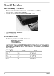
... Replacement This chapter contains step-by-step procedures on how to avoid mismatch when putting back the components. Disassembly Requirements To disassemble the computer, you need the following tools: • Wrist grounding strap and conductive mat for preventing electrostatic discharge • Flat screwdriver • Philips screwdriver • ...
... Replacement This chapter contains step-by-step procedures on how to avoid mismatch when putting back the components. Disassembly Requirements To disassemble the computer, you need the following tools: • Wrist grounding strap and conductive mat for preventing electrostatic discharge • Flat screwdriver • Philips screwdriver • ...
Aspire 7230/7530/7530G Service Guide
Page 56
...in that you do the following stages: • External module disassembly • Main unit disassembly • LCD module disassembly The flowcharts provided in the succeeding disassembly sections illustrate the entire disassembly sequence. For example, if you want to the system and ... Remove the battery pack. Main Screw List Screw Quantity Part No. Disassembly Process The disassembly process is divided into the following : 1. General Information Pre-disassembly Instructions Before proceeding with the disassembly procedure, make sure that order. Place the system on a flat, ...
...in that you do the following stages: • External module disassembly • Main unit disassembly • LCD module disassembly The flowcharts provided in the succeeding disassembly sections illustrate the entire disassembly sequence. For example, if you want to the system and ... Remove the battery pack. Main Screw List Screw Quantity Part No. Disassembly Process The disassembly process is divided into the following : 1. General Information Pre-disassembly Instructions Before proceeding with the disassembly procedure, make sure that order. Place the system on a flat, ...

Aspire 7230/7530/7530G Service Guide
Page 57
For example, if you want to remove the main board, you on the entire disassembly sequence and instructs you must first remove the keyboard, then disassemble the inside assembly frame in that need to be removed during servicing. Screw List Step MXM Module TV Tuner Module WLAN Module HDD ... M3*0.5+3.5 M2*2.5 Quantity 4 2 2 2 4 2 Part No. N/A 86.ARE07.002 86.ARE07.002 86.ARE07.002 86.A03V7.011 86.A03V7.007 Chapter 3 47 External Module Disassembly Process External Modules Disassembly Flowchart The flowchart below gives you a graphic representation on the components that order.
For example, if you want to remove the main board, you on the entire disassembly sequence and instructs you must first remove the keyboard, then disassemble the inside assembly frame in that need to be removed during servicing. Screw List Step MXM Module TV Tuner Module WLAN Module HDD ... M3*0.5+3.5 M2*2.5 Quantity 4 2 2 2 4 2 Part No. N/A 86.ARE07.002 86.ARE07.002 86.ARE07.002 86.A03V7.011 86.A03V7.007 Chapter 3 47 External Module Disassembly Process External Modules Disassembly Flowchart The flowchart below gives you a graphic representation on the components that order.

Aspire 7230/7530/7530G Service Guide
Page 70
Main Unit Disassembly Process Main Unit Disassembly Flowchart Screw List Step Switch Cover Switch Board Modem Module LCD Module Upper Cover Touch Pad Bracket Screw M2.5*3 M2.5*6.5 M2*3 M2*3 M2.5*6.5 M2.5*6.5 M2.5*3 M2.5*6.5 M2*3 M2.5*3 M2*3 60 Quantity 4 5 2 2 2 4 1 11 1 4 4 Part No. 86.T25V7.012 86.ARE07.001 86.ARE07.002 86.ARE07.002 86.ARE07.001 86.ARE07.001 86.T25V7.012 86.ARE07.001 86.ARE07.002 86.T25V7.012 86.ARE07.002 Chapter 3
Main Unit Disassembly Process Main Unit Disassembly Flowchart Screw List Step Switch Cover Switch Board Modem Module LCD Module Upper Cover Touch Pad Bracket Screw M2.5*3 M2.5*6.5 M2*3 M2*3 M2.5*6.5 M2.5*6.5 M2.5*3 M2.5*6.5 M2*3 M2.5*3 M2*3 60 Quantity 4 5 2 2 2 4 1 11 1 4 4 Part No. 86.T25V7.012 86.ARE07.001 86.ARE07.002 86.ARE07.002 86.ARE07.001 86.ARE07.001 86.T25V7.012 86.ARE07.001 86.ARE07.002 86.T25V7.012 86.ARE07.002 Chapter 3

Aspire 7230/7530/7530G Service Guide
Page 76
... before attempting to prevent stripping. otherwise, disconnect all three cables at this time to remove the cable connectors. Remove the Keyboard. IMPORTANT:Use tweezers to disassemble the upper and lower bases. 66 Chapter 3 See "Removing the WLAN Module" on page 64. 4. Do not pull on page 50. 3. See "Removing the Lower...
... before attempting to prevent stripping. otherwise, disconnect all three cables at this time to remove the cable connectors. Remove the Keyboard. IMPORTANT:Use tweezers to disassemble the upper and lower bases. 66 Chapter 3 See "Removing the WLAN Module" on page 64. 4. Do not pull on page 50. 3. See "Removing the Lower...
Aspire 7230/7530/7530G Service Guide
Page 141
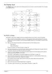
... battery and holding down the power button for specific model procedures. 2. Restart the computer. If the POST or video appears on the external display, see "Disassembly Process" on page 133. 5. Drain any memory cards and CD/DVD discs. Remove the drives (see "LCD Failure" on page 46). 8. If the Issue is...
... battery and holding down the power button for specific model procedures. 2. Restart the computer. If the POST or video appears on the external display, see "Disassembly Process" on page 133. 5. Drain any memory cards and CD/DVD discs. Remove the drives (see "LCD Failure" on page 46). 8. If the Issue is...
Aspire 7230/7530/7530G Service Guide
Page 142
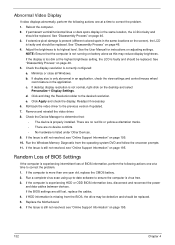
...computer is experiencing intermittent loss of BIOS information, perform the following actions one at a time to the previous version if updated. 7. See "Disassembly Process" on page 46. 5. Minimize or close all Windows. b. Check the Device Manager to its highest level. If the Issue is ..." on page 195. Replace the Motherboard. 6. Adjust the brightness to determine that the computer is not running on page 46. 4. See "Disassembly Process" on page 46. 3. If display size is experiencing HDD or ODD BIOS information loss, disconnect and reconnect the power and data cables...
...computer is experiencing intermittent loss of BIOS information, perform the following actions one at a time to the previous version if updated. 7. See "Disassembly Process" on page 46. 5. Minimize or close all Windows. b. Check the Device Manager to its highest level. If the Issue is ..." on page 195. Replace the Motherboard. 6. Adjust the brightness to determine that the computer is not running on page 46. 4. See "Disassembly Process" on page 46. 3. If display size is experiencing HDD or ODD BIOS information loss, disconnect and reconnect the power and data cables...
Aspire 7230/7530/7530G Service Guide
Page 147
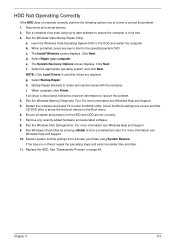
... date using up-to-date software to resolve the problem. 4. Startup Repair attempts to enter the BIOS Utility. If the issue is virus free. 3. See "Disassembly Process" on the HDD and ODD are required. When prompted, press any recently added hardware and associated software. 8. f. For more information see Windows Help and...
... date using up-to-date software to resolve the problem. 4. Startup Repair attempts to enter the BIOS Utility. If the issue is virus free. 3. See "Disassembly Process" on the HDD and ODD are required. When prompted, press any recently added hardware and associated software. 8. f. For more information see Windows Help and...
Aspire 7230/7530/7530G Service Guide
Page 150
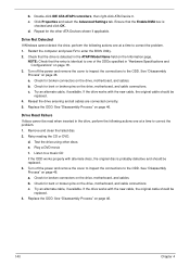
... perform the following actions one at a time to the ODD. Reseat the drive ensuring and all cables are connected correctly. 5. See "Disassembly Process" on the Information page. If the drive works with the new cable, the original cable should be replaced. 3. e. Test the...select the Advanced Settings tab. Ensure that the drive is probably defective and should be replaced. 4. Listen to correct the problem. 1. See "Disassembly Process" on page 46. b. Check for broken connectors on page 46. Try an alternate cable, if available. b. Double-click IDE ATA/...
... perform the following actions one at a time to the ODD. Reseat the drive ensuring and all cables are connected correctly. 5. See "Disassembly Process" on the Information page. If the drive works with the new cable, the original cable should be replaced. 3. e. Test the...select the Advanced Settings tab. Ensure that the drive is probably defective and should be replaced. 4. Listen to correct the problem. 1. See "Disassembly Process" on page 46. b. Check for broken connectors on page 46. Try an alternate cable, if available. b. Double-click IDE ATA/...

Aspire 7230/7530/7530G Service Guide
Page 208
LCD Brackets 96 LCD Failure 133 LCD Module Disassembly Flowchart 89 LCD Panel 94 lower covers 50 M Main Unit Disassembly Flowchart 60 Mainboard 85 media access on indicator 10 MediaTouch Button Failure 143 Memory Check 130 Model Definition 172 Modem Board 65 Modem Failure 141 N ...
LCD Brackets 96 LCD Failure 133 LCD Module Disassembly Flowchart 89 LCD Panel 94 lower covers 50 M Main Unit Disassembly Flowchart 60 Mainboard 85 media access on indicator 10 MediaTouch Button Failure 143 Memory Check 130 Model Definition 172 Modem Board 65 Modem Failure 141 N ...


