Service Guide
Page 7
Table of Contents System Specifications 1 Features 1 System Block Diagram 6 UMA 6 Discrete (nVidia 7 Discrete (ATI 8 Your Acer Notebook tour 9 Top View 9 Rear view 10 Left View 11 Right View 12 Base view 13 Indicators 14 Touch Pad Basics...BIOS Utility 31 Aspire 5742/5742G/5742Z/5742ZG BIOS 32 Information 32 Main 33 Security 34 Boot 37 Exit 38 BIOS Flash Utilities 39 DOS Flash Utility 40 WinFlash Utility 41 Remove HDD/BIOS Password Utilities 42 Machine Disassembly and Replacement 47 Disassembly Requirements 47 Pre-disassembly Instructions 48 Disassembly Process 49 ...
Table of Contents System Specifications 1 Features 1 System Block Diagram 6 UMA 6 Discrete (nVidia 7 Discrete (ATI 8 Your Acer Notebook tour 9 Top View 9 Rear view 10 Left View 11 Right View 12 Base view 13 Indicators 14 Touch Pad Basics...BIOS Utility 31 Aspire 5742/5742G/5742Z/5742ZG BIOS 32 Information 32 Main 33 Security 34 Boot 37 Exit 38 BIOS Flash Utilities 39 DOS Flash Utility 40 WinFlash Utility 41 Remove HDD/BIOS Password Utilities 42 Machine Disassembly and Replacement 47 Disassembly Requirements 47 Pre-disassembly Instructions 48 Disassembly Process 49 ...
Service Guide
Page 8
... 85 Removing the Thermal Module 89 Removing the CPU 91 Removing the LCD Module 92 Removing the DC-In Assembly 96 LCD Module Disassembly Process 97 LCD Module Disassembly Flowchart 97 Removing the LCD Bezel 98 Removing the CCD Module 100 Removing the Inverter Module (LCD Only 101 Removing the LCD/LED...
... 85 Removing the Thermal Module 89 Removing the CPU 91 Removing the LCD Module 92 Removing the DC-In Assembly 96 LCD Module Disassembly Process 97 LCD Module Disassembly Flowchart 97 Removing the LCD Bezel 98 Removing the CCD Module 100 Removing the Inverter Module (LCD Only 101 Removing the LCD/LED...
Service Guide
Page 57
...with the corresponding components to disassemble the notebook computer for the different components vary in size. Chapter 3 47 This chapter contains step-by-step procedures on how to avoid mismatch when putting back the components. Chapter 3 Machine Disassembly and Replacement IMPORTANT: The ...outside housing and color may vary from the mass produced model. Disassembly Requirements To disassemble the computer, you need the following tools: • Wrist grounding strap ...
...with the corresponding components to disassemble the notebook computer for the different components vary in size. Chapter 3 47 This chapter contains step-by-step procedures on how to avoid mismatch when putting back the components. Chapter 3 Machine Disassembly and Replacement IMPORTANT: The ...outside housing and color may vary from the mass produced model. Disassembly Requirements To disassemble the computer, you need the following tools: • Wrist grounding strap ...
Service Guide
Page 58
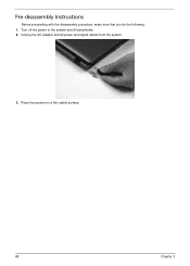
Place the system on a flat, stable surface. 48 Chapter 3 Unplug the AC adapter and all peripherals. 2. Turn off the power to the system and all power and signal cables from the system. 3. Pre-disassembly Instructions Before proceeding with the disassembly procedure, make sure that you do the following: 1.
Place the system on a flat, stable surface. 48 Chapter 3 Unplug the AC adapter and all peripherals. 2. Turn off the power to the system and all power and signal cables from the system. 3. Pre-disassembly Instructions Before proceeding with the disassembly procedure, make sure that you do the following: 1.
Service Guide
Page 59
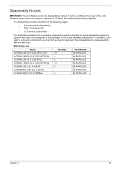
..., such as the camera, antenna or LCD panel, the whole module must first remove the keyboard, then disassemble the inside assembly frame in the succeeding disassembly sections illustrate the entire disassembly sequence. If any of the hardware components. Main Screw List Screw Quantity Part Number SCREW 2.5D 5L K... to remove the mainboard, you must be replaced. For example, if you want to any part of factory conditions. Disassembly Process IMPORTANT: The LCD Module cannot be disassembled outside of the LCD Module is divided into the following stages: • External module...
..., such as the camera, antenna or LCD panel, the whole module must first remove the keyboard, then disassemble the inside assembly frame in the succeeding disassembly sections illustrate the entire disassembly sequence. If any of the hardware components. Main Screw List Screw Quantity Part Number SCREW 2.5D 5L K... to remove the mainboard, you must be replaced. For example, if you want to any part of factory conditions. Disassembly Process IMPORTANT: The LCD Module cannot be disassembled outside of the LCD Module is divided into the following stages: • External module...
Service Guide
Page 60
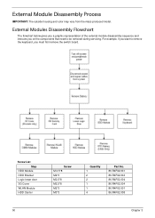
...*3 Quantity 1 2 2 1 1 4 Part No. 86.R4F02.001 86.R4F02.004 86.R4F02.004 86.R4F02.004 86.R4F02.001 86.R4F02.008 50 Chapter 3 External Module Disassembly Process IMPORTANT: The outside housing and color may vary from the mass produced model. External Modules...
...*3 Quantity 1 2 2 1 1 4 Part No. 86.R4F02.001 86.R4F02.004 86.R4F02.004 86.R4F02.004 86.R4F02.001 86.R4F02.008 50 Chapter 3 External Module Disassembly Process IMPORTANT: The outside housing and color may vary from the mass produced model. External Modules...
Service Guide
Page 76
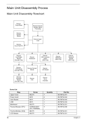
Main Unit Disassembly Process Main Unit Disassembly Flowchart Screw List Step Upper Cover Power board Card Reader USB Mainboard Thermal Module (CPU) Thermal Module (VGA) LCD Module 66 Screw M2.5*5 M2*3 M2*3 M2*3 M2.5*5 SCREW ASSY CPU THERMAL M2.5*5 M2.5*5 Quantity 7 2 1 1 1 4 2 4 Part No. 86.R4F02.001 86.R4F02.004 86.R4F02.004 86.R4F02.004 86.R4F02.001 86.R4F02.008 86.R4F02.001 86.R4F02.001 Chapter 3
Main Unit Disassembly Process Main Unit Disassembly Flowchart Screw List Step Upper Cover Power board Card Reader USB Mainboard Thermal Module (CPU) Thermal Module (VGA) LCD Module 66 Screw M2.5*5 M2*3 M2*3 M2*3 M2.5*5 SCREW ASSY CPU THERMAL M2.5*5 M2.5*5 Quantity 7 2 1 1 1 4 2 4 Part No. 86.R4F02.001 86.R4F02.004 86.R4F02.004 86.R4F02.004 86.R4F02.001 86.R4F02.008 86.R4F02.001 86.R4F02.001 Chapter 3
Service Guide
Page 77
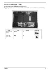
See "External Module Disassembly Process" on page 50. 2. Turn the computer over. Remove the eleven (11) screws from the lower cover and four (4) screws from the battery bay. Step Upper Cover (red callout) Size M2.5*8 Battery Bay (green callout) M2*3 Quantity 11 4 Screw Type Chapter 3 67 Removing the Upper Cover 1.
See "External Module Disassembly Process" on page 50. 2. Turn the computer over. Remove the eleven (11) screws from the lower cover and four (4) screws from the battery bay. Step Upper Cover (red callout) Size M2.5*8 Battery Bay (green callout) M2*3 Quantity 11 4 Screw Type Chapter 3 67 Removing the Upper Cover 1.

Service Guide
Page 107
LCD Module Disassembly Process LCD Module Disassembly Flowchart Screw List Step LCD Bezel LCD Brackets (top) LCD Hinges Inverter Module LCD Brackets (side) Screw M2.5*6 M2.5*5 M2.5*5 M2.5*5 M2*3 Quantity 2 2 2 1 6 Part No. 86.R4F02.003 86.R4F02.001 86.R4F02.001 86.R4F02.001 86.R4F02.004 Chapter 3 97
LCD Module Disassembly Process LCD Module Disassembly Flowchart Screw List Step LCD Bezel LCD Brackets (top) LCD Hinges Inverter Module LCD Brackets (side) Screw M2.5*6 M2.5*5 M2.5*5 M2.5*5 M2*3 Quantity 2 2 2 1 6 Part No. 86.R4F02.003 86.R4F02.001 86.R4F02.001 86.R4F02.001 86.R4F02.004 Chapter 3 97
Service Guide
Page 108
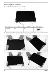
Starting from the bottom edge of the bezel, pry the bezel upwards and away from all locking latches. 98 Chapter 3 Remove the two (2) bezel screw caps and two (2) screws securing the bezel to the LCD module. Step LCD Bezel Size M2.5*6 Quantity 2 Screw Type 3. Continue along the left, top, and right sides until the bezel is free from the panel. Removing the LCD Bezel 1. See "Main Unit Disassembly Process" on page 66. 2.
Starting from the bottom edge of the bezel, pry the bezel upwards and away from all locking latches. 98 Chapter 3 Remove the two (2) bezel screw caps and two (2) screws securing the bezel to the LCD module. Step LCD Bezel Size M2.5*6 Quantity 2 Screw Type 3. Continue along the left, top, and right sides until the bezel is free from the panel. Removing the LCD Bezel 1. See "Main Unit Disassembly Process" on page 66. 2.
Service Guide
Page 172
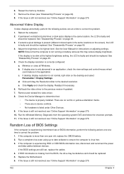
... the computer. 2. d. Roll back the video driver to its highest level. Reseat the memory modules. 7. Remove the drives (see "Disassembly Process" on adjusting settings. Abnormal Video Display If video displays abnormally, perform the following actions one at a time to determine that the computer... LCD is experiencing intermittent loss of BIOS information, perform the following actions one at a time to correct the problem. 1. See "Disassembly Process" on page 279. 162 Chapter 4 Check the display resolution is only abnormal in an application, check the view settings and ...
... the computer. 2. d. Roll back the video driver to its highest level. Reseat the memory modules. 7. Remove the drives (see "Disassembly Process" on adjusting settings. Abnormal Video Display If video displays abnormally, perform the following actions one at a time to determine that the computer... LCD is experiencing intermittent loss of BIOS information, perform the following actions one at a time to correct the problem. 1. See "Disassembly Process" on page 279. 162 Chapter 4 Check the display resolution is only abnormal in an application, check the view settings and ...
Service Guide
Page 178
... entering chkdsk /r from a known good date using up-to-date software to the operating system DVD. For more information see Windows Help and Support. 5. See "Disassembly Process" on the Boot menu. 6. e. Startup Repair attempts to correct the problem. 1. Run the Windows Memory Diagnostic Tool. Remove any key to start to ensure...
... entering chkdsk /r from a known good date using up-to-date software to the operating system DVD. For more information see Windows Help and Support. 5. See "Disassembly Process" on the Boot menu. 6. e. Startup Repair attempts to correct the problem. 1. Run the Windows Memory Diagnostic Tool. Remove any key to start to ensure...
Service Guide
Page 181
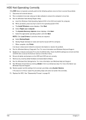
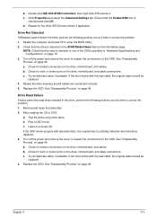
... the original disc is checked and click OK. Turn off the power and remove the cover to inspect the connections to the ODD. See "Disassembly Process" on page 49. c. Replace the ODD. Play a DVD movie f. e. b. b. c. Click Properties and select the Advanced Settings... tab. If the drive works with the new cable, the original cable should be replaced. 3. See "Disassembly Process" on page 49. Check for bent or broken pins on the drive, motherboard, and cable connections. Double-click IDE ATA/ATAPI controllers, ...
... the original disc is checked and click OK. Turn off the power and remove the cover to inspect the connections to the ODD. See "Disassembly Process" on page 49. c. Replace the ODD. Play a DVD movie f. e. b. b. c. Click Properties and select the Advanced Settings... tab. If the drive works with the new cable, the original cable should be replaced. 3. See "Disassembly Process" on page 49. Check for bent or broken pins on the drive, motherboard, and cable connections. Double-click IDE ATA/ATAPI controllers, ...


