
Acer Aspire 5739G Notebook Series Start Guide
Page 3
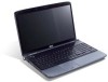
The Aspire Series Generic User Guide contains useful information applying to complete the installation. The Quick Guide introduces you for making an Acer notebook your choice for Starters... Follow the instructions on such subjects as using the keyboard and audio, etc. 3 First things first We would like... to thank you to the basic features and functions of your new computer. Such instances are only contained in the Aspire ...
The Aspire Series Generic User Guide contains useful information applying to complete the installation. The Quick Guide introduces you for making an Acer notebook your choice for Starters... Follow the instructions on such subjects as using the keyboard and audio, etc. 3 First things first We would like... to thank you to the basic features and functions of your new computer. Such instances are only contained in the Aspire ...
Acer Aspire 5739G Notebook Series Start Guide
Page 5
...Bluetooth communication button/indicator Enables/disables the Bluetooth function. Battery1 Indicates the computer's battery status. 1. Protection fingerprint reader supporting Acer FingerNav 4-way control function (only for certain models). 11 Palmrest Comfortable support area for your computer. 8 Touchpad Touch-sensitive..., The left and right mouse buttons. *The center button serves as Acer Bio- Indicates the status of wireless button/indicator LAN communication. with mute and hold keys. 7 Keyboard For entering data into your hands when you use the computer. 12...
...Bluetooth communication button/indicator Enables/disables the Bluetooth function. Battery1 Indicates the computer's battery status. 1. Protection fingerprint reader supporting Acer FingerNav 4-way control function (only for certain models). 11 Palmrest Comfortable support area for your computer. 8 Touchpad Touch-sensitive..., The left and right mouse buttons. *The center button serves as Acer Bio- Indicates the status of wireless button/indicator LAN communication. with mute and hold keys. 7 Keyboard For entering data into your hands when you use the computer. 12...

Acer Aspire 5739G Notebook Series Start Guide
Page 12
...8226; • • • Special keys • and controls • I/O interface • • • Acer Video Conference, featuring: • Integrated Acer Crystal Eye webcam* • Acer PureZone technology* WLAN: Intel® Wireless WiFi Link 5100/5300* WPAN: Bluetooth® 2.1+Enhanced Data Rate (EDR)* Modem: ....8 W 4400 mAh* 3-pin 65 W AC adapter* 3-pin 90 W AC adapter* ENERGY STAR® 103-/104-/107-key keyboard Touchpad pointing device Acer Bio-Protection fingerprint reader* 5-in-1 card reader (SD/MMC/MS/MS PRO/xD) USB 2.0 port HDMI™ port with HDCP...
...8226; • • • Special keys • and controls • I/O interface • • • Acer Video Conference, featuring: • Integrated Acer Crystal Eye webcam* • Acer PureZone technology* WLAN: Intel® Wireless WiFi Link 5100/5300* WPAN: Bluetooth® 2.1+Enhanced Data Rate (EDR)* Modem: ....8 W 4400 mAh* 3-pin 65 W AC adapter* 3-pin 90 W AC adapter* ENERGY STAR® 103-/104-/107-key keyboard Touchpad pointing device Acer Bio-Protection fingerprint reader* 5-in-1 card reader (SD/MMC/MS/MS PRO/xD) USB 2.0 port HDMI™ port with HDCP...
Acer Aspire 5739G Series Service Guide
Page 7
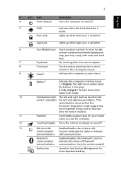
... 1 Features 1 System Block Diagram 4 Your Acer Notebook tour 5 Front View 5 Hot Keys 7 Closed Front View 7 Rear View 8 Left View 8 Right View 9 Bottom View 10 Touchpad Basics (with fingerprint reader 11 Using the Keyboard 12 Lock Keys and embedded numeric keypad 12 Windows... Keys 13 Special Key 14 Using the System Utilities 15 Acer GridVista (dual-display compatible 15 Hardware Specifications and Configurations 17 System Utilities...
... 1 Features 1 System Block Diagram 4 Your Acer Notebook tour 5 Front View 5 Hot Keys 7 Closed Front View 7 Rear View 8 Left View 8 Right View 9 Bottom View 10 Touchpad Basics (with fingerprint reader 11 Using the Keyboard 12 Lock Keys and embedded numeric keypad 12 Windows... Keys 13 Special Key 14 Using the System Utilities 15 Acer GridVista (dual-display compatible 15 Hardware Specifications and Configurations 17 System Utilities...
Acer Aspire 5739G Series Service Guide
Page 8
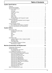
...Removing the Hinge Covers 63 Removing the Switch Cover 63 Removing the Power Save Board 66 Removing the Power Switch Board 67 Removing the Keyboard 67 Removing the LCD Module 68 Removing the Upper Base 72 Removing the Finger Print Reader 75 Removing the Multifunction Board 77 Removing ...105 Replacing the Modem Module 107 Replacing the Finger Print Reader 109 Replacing the Upper Cover 109 Replacing the LCD Module 113 Replacing the Keyboard 116 Replacing the Power Switch Board 116 Replacing the Power Save Board 117 Replacing the Switch Cover 118 Replacing the Hinge Covers 120 ...
...Removing the Hinge Covers 63 Removing the Switch Cover 63 Removing the Power Save Board 66 Removing the Power Switch Board 67 Removing the Keyboard 67 Removing the LCD Module 68 Removing the Upper Base 72 Removing the Finger Print Reader 75 Removing the Multifunction Board 77 Removing ...105 Replacing the Modem Module 107 Replacing the Finger Print Reader 109 Replacing the Upper Cover 109 Replacing the LCD Module 113 Replacing the Keyboard 116 Replacing the Power Switch Board 116 Replacing the Power Save Board 117 Replacing the Switch Cover 118 Replacing the Hinge Covers 120 ...

Acer Aspire 5739G Series Service Guide
Page 9
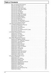
... Common Problems 133 Power On Issue 134 No Display Issue 136 Random Loss of BIOS Settings 138 LCD Failure 139 Built-In Keyboard Failure 139 Touchpad Failure 140 Internal Speaker Failure 140 Internal Microphone Failure 142 HDD Not Operating Correctly 144 ODD Failure 145 USB ...165 BIOS Recovery by Crisis Disk 167 FRU (Field Replaceable Unit) List 169 Aspire 5739 Exploded Diagrams 170 Main Module 170 Aspire 5739 FRU List 171 Screw List 179 Model Definition and Configuration 181 Aspire 5739 Series 181 Test Compatible Components 209 Microsoft® Windows® Vista ...
... Common Problems 133 Power On Issue 134 No Display Issue 136 Random Loss of BIOS Settings 138 LCD Failure 139 Built-In Keyboard Failure 139 Touchpad Failure 140 Internal Speaker Failure 140 Internal Microphone Failure 142 HDD Not Operating Correctly 144 ODD Failure 145 USB ...165 BIOS Recovery by Crisis Disk 167 FRU (Field Replaceable Unit) List 169 Aspire 5739 Exploded Diagrams 170 Main Module 170 Aspire 5739 FRU List 171 Screw List 179 Model Definition and Configuration 181 Aspire 5739 Series 181 Test Compatible Components 209 Microsoft® Windows® Vista ...
Acer Aspire 5739G Series Service Guide
Page 12
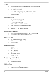
...16.14 x 11.25 x 1.37/1.63 inches) • 2.8 kg (5.07 lbs.) withone HDD and 8-cell battery pack Privacy control • Acer Bio-Protection fingerprint solution* • BIOS user, supervisor, HDD passwords • Kensington lock slot Power subsystem • ACPI 3.0 • •...-/104-/107-key keyboard • Touchpad pointing device I/O interface • Acer Bio-Protection fingerprint reader • 5-in stereo microphones MS-Sound compatible Communication • Acer Video Conference, featuring: • Integrated Acer Crystal Eye webcam* • Acer PureZone technology •...
...16.14 x 11.25 x 1.37/1.63 inches) • 2.8 kg (5.07 lbs.) withone HDD and 8-cell battery pack Privacy control • Acer Bio-Protection fingerprint solution* • BIOS user, supervisor, HDD passwords • Kensington lock slot Power subsystem • ACPI 3.0 • •...-/104-/107-key keyboard • Touchpad pointing device I/O interface • Acer Bio-Protection fingerprint reader • 5-in stereo microphones MS-Sound compatible Communication • Acer Video Conference, featuring: • Integrated Acer Crystal Eye webcam* • Acer PureZone technology •...

Acer Aspire 5739G Series Service Guide
Page 16
Icon Item Keyboard Touchpad Power Description For entering data into power-saving mode. Battery Click buttons (left and right mouse buttons. *The center button serves as Acer BioProtection fingerprint reader supporting Acer FingerNav 4-way control function (only for certain models). The left and right ... into your hands when you use the computer. Wireless LAN Communication button / Indicator Bluetooth Communication button/indicator Backup key Acer PowerSmart key Speakers Enables/disables the wireless LAN function. Turns the internal touchpad on and off. Fully charged: The light...
Icon Item Keyboard Touchpad Power Description For entering data into power-saving mode. Battery Click buttons (left and right mouse buttons. *The center button serves as Acer BioProtection fingerprint reader supporting Acer FingerNav 4-way control function (only for certain models). The left and right ... into your hands when you use the computer. Wireless LAN Communication button / Indicator Bluetooth Communication button/indicator Backup key Acer PowerSmart key Speakers Enables/disables the wireless LAN function. Turns the internal touchpad on and off. Fully charged: The light...

Acer Aspire 5739G Series Service Guide
Page 22
... Lock does not work with the arithmetic operators +, -, *, and /). Type the letters in numeric mode. Lock Keys and embedded numeric keypad The keyboard has three lock keys which you can toggle on , the embedded keypad is in a normal manner. 12 Chapter 1 A better solution would be to... letters on , the screen moves one line up or down arrow keys respectively. When Num Lock is on embedded keypad. To simplify the keyboard legend, cursor-control key symbols are not printed on , all alphabetic characters typed are in a normal manner. The embedded numeric keypad functions...
... Lock does not work with the arithmetic operators +, -, *, and /). Type the letters in numeric mode. Lock Keys and embedded numeric keypad The keyboard has three lock keys which you can toggle on , the embedded keypad is in a normal manner. 12 Chapter 1 A better solution would be to... letters on , the screen moves one line up or down arrow keys respectively. When Num Lock is on embedded keypad. To simplify the keyboard legend, cursor-control key symbols are not printed on , all alphabetic characters typed are in a normal manner. The embedded numeric keypad functions...

Acer Aspire 5739G Series Service Guide
Page 23
Windows Keys The keyboard has two keys that perform Windows-specific functions. Key Description Windows key Pressed alone, this key has the same effect as clicking on your computer (...
Windows Keys The keyboard has two keys that perform Windows-specific functions. Key Description Windows key Pressed alone, this key has the same effect as clicking on your computer (...

Acer Aspire 5739G Series Service Guide
Page 24
... a text editor or word processor. 2. Hold and then press the key at the upper-center of the keyboard. Hold and then press the key at the upper-center of your keyboard. Please refer to www.microsoft.com/ typography/faq/faq12.htm for more information. Open a text editor or word processor. 2. The Euro...
... a text editor or word processor. 2. Hold and then press the key at the upper-center of the keyboard. Hold and then press the key at the upper-center of your keyboard. Please refer to www.microsoft.com/ typography/faq/faq12.htm for more information. Open a text editor or word processor. 2. The Euro...

Acer Aspire 5739G Series Service Guide
Page 34
VGA Graphic Controller Item Type Manufacturing Tech. Form Factor Package Keyboard AMD M92XT 55 nm 29mm*29mm M2 Specification Item Keyboard Controller Total number of keypads Windows logo key Internal & external keyboard work simultaneously Audio Interface Specification ENE KB926 86-/87-/91-key keyboard Yes Yes Item Audio Controller Features LAN Specification Realtek ALC888 Azalia...
VGA Graphic Controller Item Type Manufacturing Tech. Form Factor Package Keyboard AMD M92XT 55 nm 29mm*29mm M2 Specification Item Keyboard Controller Total number of keypads Windows logo key Internal & external keyboard work simultaneously Audio Interface Specification ENE KB926 86-/87-/91-key keyboard Yes Yes Item Audio Controller Features LAN Specification Realtek ALC888 Azalia...
Acer Aspire 5739G Series Service Guide
Page 58
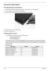
... • External module disassembly • Main unit disassembly • LCD module disassembly The flowcharts provided in that you must first remove the keyboard, then disassemble the inside assembly frame in the succeeding disassembly sections illustrate the entire disassembly sequence. Main Screw List Description Quantity... Acer P/N M2.0D 3.0L K4.6D 0.8T ZK 17 86.AD302.001 M2.5D 3.0L K5.5D 0.8T ZK 15 86.AD302.002 M2....
... • External module disassembly • Main unit disassembly • LCD module disassembly The flowcharts provided in that you must first remove the keyboard, then disassemble the inside assembly frame in the succeeding disassembly sections illustrate the entire disassembly sequence. Main Screw List Description Quantity... Acer P/N M2.0D 3.0L K4.6D 0.8T ZK 17 86.AD302.001 M2.5D 3.0L K5.5D 0.8T ZK 15 86.AD302.002 M2....
Acer Aspire 5739G Series Service Guide
Page 59
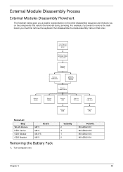
... Disassembly Process External Modules Disassembly Flowchart The flowchart below gives you a graphic representation on the entire disassembly sequence and instructs you must first remove the keyboard, then disassemble the inside assembly frame in that need to remove the main board, you on the components that order. For example, if you want...
... Disassembly Process External Modules Disassembly Flowchart The flowchart below gives you a graphic representation on the entire disassembly sequence and instructs you must first remove the keyboard, then disassemble the inside assembly frame in that need to remove the main board, you on the components that order. For example, if you want...

Acer Aspire 5739G Series Service Guide
Page 72
Main Unit Disassembly Process Main Unit Disassembly Flowchart Remove External Modules before proceeding Rem ove Hinge Covers Rem ove Switch Cover Rem ove Keyboard Rem ove Power Saving Board Rem ove Power Board Rem ove LCD Module Upper Cover Rem ove Upper Cover Rem ove Fingerprint Reader Rem ove ...
Main Unit Disassembly Process Main Unit Disassembly Flowchart Remove External Modules before proceeding Rem ove Hinge Covers Rem ove Switch Cover Rem ove Keyboard Rem ove Power Saving Board Rem ove Power Board Rem ove LCD Module Upper Cover Rem ove Upper Cover Rem ove Fingerprint Reader Rem ove ...

Acer Aspire 5739G Series Service Guide
Page 75
Using both hands, lift both sides of the rear edge of the Switch Cover upward as shown. Disconnect the function board from the main unit by lifting the FFC lock and removing the FFC as shown. 7. Chapter 3 65 6. Place the switch board on the keyboard. 8.
Using both hands, lift both sides of the rear edge of the Switch Cover upward as shown. Disconnect the function board from the main unit by lifting the FFC lock and removing the FFC as shown. 7. Chapter 3 65 6. Place the switch board on the keyboard. 8.

Acer Aspire 5739G Series Service Guide
Page 77
... 3 67 Remove the power board by sliding it out from the Switch Cover. Pull up on the center rear of the keyboard until the Keyboard snaps free of the securing tabs on page 68. 2. 4. Step Switch Cover (red callout) Size M2.5*4 Quantity 3 3. See "Removing the Switch ...Cover" on page 63. 2. Screw Type Removing the Keyboard 1. Removing the Power Switch Board 1. Remove the three screws securing the Power Save Board to the Switch Cover as shown. Remove the Power Save Board...
... 3 67 Remove the power board by sliding it out from the Switch Cover. Pull up on the center rear of the keyboard until the Keyboard snaps free of the securing tabs on page 68. 2. 4. Step Switch Cover (red callout) Size M2.5*4 Quantity 3 3. See "Removing the Switch ...Cover" on page 63. 2. Screw Type Removing the Keyboard 1. Removing the Power Switch Board 1. Remove the three screws securing the Power Save Board to the Switch Cover as shown. Remove the Power Save Board...

Acer Aspire 5739G Series Service Guide
Page 78
See "Removing the WLAN Module" on page 67. 68 Chapter 3 Remove the keyboard from the Mainboard. 5. IMPORTANT:The keyboard is still attached to remove it from the chassis. Unlock the connector and pull the FFC to the Mainboard FFC - See "Removing the Keyboard" on page 52. 2. do not pull on the touchpad. 4. Removing the LCD Module 1. Lay the keyboard face down on the keyboard. 3.
See "Removing the WLAN Module" on page 67. 68 Chapter 3 Remove the keyboard from the Mainboard. 5. IMPORTANT:The keyboard is still attached to remove it from the chassis. Unlock the connector and pull the FFC to the Mainboard FFC - See "Removing the Keyboard" on page 52. 2. do not pull on the touchpad. 4. Removing the LCD Module 1. Lay the keyboard face down on the keyboard. 3.

Acer Aspire 5739G Series Service Guide
Page 126
Insert the Keyboard, front edge first, into the Switch Cover by sliding it in place. Press down both sides of the keyboard to the Mainboard. 2. Replacing the Power Switch Board 1. Place the Keyboard on the Upper Cover, face up and reconnect the FFC cable to secure it under the securing tab as shown. Ensure that the six tabs are correctly seated. 3. Insert the the Power Board into the Upper Cover as shown. 116 Chapter 3 Replacing the Keyboard 1.
Insert the Keyboard, front edge first, into the Switch Cover by sliding it in place. Press down both sides of the keyboard to the Mainboard. 2. Replacing the Power Switch Board 1. Place the Keyboard on the Upper Cover, face up and reconnect the FFC cable to secure it under the securing tab as shown. Ensure that the six tabs are correctly seated. 3. Insert the the Power Board into the Upper Cover as shown. 116 Chapter 3 Replacing the Keyboard 1.
Acer Aspire 5739G Series Service Guide
Page 128
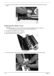
Place the switch board on page 49. 2. 4. It is recommended that only fingers are used to the outer casing. See "Removing the Battery Pack" on the keyboard. 4. Replacing the Switch Cover CAUTION: Using tools to remove the Switch Cover may cause damage to remove the Switch Cover. 1. Connect the power board to the Function Board by inserting the FFC and closing the FFC lock as shown. 118 Chapter 3 Connect the Power Save Board to the main unit by inserting the FFC and closing the FFC lock as shown. See "Removing the Hinge Covers" on page 63. 3.
Place the switch board on page 49. 2. 4. It is recommended that only fingers are used to the outer casing. See "Removing the Battery Pack" on the keyboard. 4. Replacing the Switch Cover CAUTION: Using tools to remove the Switch Cover may cause damage to remove the Switch Cover. 1. Connect the power board to the Function Board by inserting the FFC and closing the FFC lock as shown. 118 Chapter 3 Connect the Power Save Board to the main unit by inserting the FFC and closing the FFC lock as shown. See "Removing the Hinge Covers" on page 63. 3.


