Aspire 5739G Graphics Card - Acer
Aspire 5739G Graphics Card

Related Manual Pages


Similar Questions

Update My Graphics Card
I want to update my graphics card. many time i installing a bluestacks application n it doest intall...
I want to update my graphics card. many time i installing a bluestacks application n it doest intall...
(Posted by karanprajapati64 10 years ago)

Can I Add Graphic Card In Acer Aspire 5536g Laptop?
Can I Add "ZOTAC GT 610 2GB DDR3 Synergy Edition Graphic Card" in Acer Aspire 5536G?
Can I Add "ZOTAC GT 610 2GB DDR3 Synergy Edition Graphic Card" in Acer Aspire 5536G?
(Posted by pawandebbarma 10 years ago)

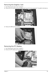
Replacing The Graphic Card
Hi. The graphics card is not working and I am considering to replace it. I would like to know what g...
Hi. The graphics card is not working and I am considering to replace it. I would like to know what g...
(Posted by justinfarrugia27 12 years ago)