Aspire 5335 / 5735 / 5735Z Service Guide
Page 7
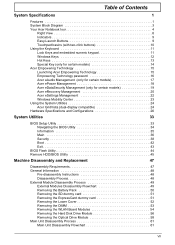
...Acer Notebook tour 4 Right View 6 Indicators 9 Easy-Launch Buttons 9 Touchpad basics (with two-click buttons 10 Using the Keyboard 11 Lock Keys and embedded numeric keypad 11 Windows Keys 12 Hot Keys 13 Special Key (only for certain models 14 Acer Empowering Technology 15 Launching Acer... 44 Remove HDD/BIOS Utility 45 Machine Disassembly and Replacement 47 Disassembly Requirements 47 General Information 48 Pre-disassembly Instructions 48 Disassembly Process 48 External Module Disassembly Process 49 External Modules Disassembly Flowchart 49 Removing the Battery Pack 50 ...
...Acer Notebook tour 4 Right View 6 Indicators 9 Easy-Launch Buttons 9 Touchpad basics (with two-click buttons 10 Using the Keyboard 11 Lock Keys and embedded numeric keypad 11 Windows Keys 12 Hot Keys 13 Special Key (only for certain models 14 Acer Empowering Technology 15 Launching Acer... 44 Remove HDD/BIOS Utility 45 Machine Disassembly and Replacement 47 Disassembly Requirements 47 General Information 48 Pre-disassembly Instructions 48 Disassembly Process 48 External Module Disassembly Process 49 External Modules Disassembly Flowchart 49 Removing the Battery Pack 50 ...
Aspire 5335 / 5735 / 5735Z Service Guide
Page 8
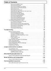
... Case 70 Removing the LED Board 73 Removing the Speaker Module 75 Removing the Touchpad Module 77 Removing the Modem Board 80 Removing the Main Board 82 Removing the ...USB Board Module 84 Removing the Bluetooth Modules 86 LCD Module Disassembly Process 87 LCD Module Disassembly Flowchart 87 Removing the LCD Bezel 88 Removing the LCD panel with ...Crisis Disk 120 FRU (Field Replaceable Unit) List 121 Aspire 5735/5735Z/5335 Series Exploded Diagram 122 Model Definition and Configuration 130 Aspire 5735/5735Z/5335 Series 130 Test Compatible Components 155 Microsoft®...
... Case 70 Removing the LED Board 73 Removing the Speaker Module 75 Removing the Touchpad Module 77 Removing the Modem Board 80 Removing the Main Board 82 Removing the ...USB Board Module 84 Removing the Bluetooth Modules 86 LCD Module Disassembly Process 87 LCD Module Disassembly Flowchart 87 Removing the LCD Bezel 88 Removing the LCD panel with ...Crisis Disk 120 FRU (Field Replaceable Unit) List 121 Aspire 5735/5735Z/5335 Series Exploded Diagram 122 Model Definition and Configuration 130 Aspire 5735/5735Z/5335 Series 130 Test Compatible Components 155 Microsoft®...
Aspire 5335 / 5735 / 5735Z Service Guide
Page 71
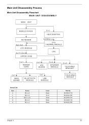
Main Unit Disassembly Process Main Unit Disassembly Flowchart MAIN UNIT DISASSEMBLY MAIN UNIT MIDDLE COVER KEYBOARD Ax2, Ex2 LCD MODULE A x 11, G x 4 UPPER CASE C x 1 HEAT SINK FAN SCREW X 4 CPU THERMAL MODULE CPU C x 1 MODEM CARD C x 1 LED BOARD C x 4 SPEAKER MODULE C x 2 TOUCHPAD BRACKET Cx1 MAIN BOARD BLUETOOTH MODULE Cx1 USB MODULE TOUCHPAD MODULE Screw List Item A C E G H Screw M2 x L8 M2 x L3 M2.5 x L10 M2 x L4 M2 x L3 Color Black Silver Silver Black Black Part No. 86.00E34.738 86.9A522.3R0 86.00F84.73A 86.00A02.140 86.9A552.3R0 Chapter 3 61
Main Unit Disassembly Process Main Unit Disassembly Flowchart MAIN UNIT DISASSEMBLY MAIN UNIT MIDDLE COVER KEYBOARD Ax2, Ex2 LCD MODULE A x 11, G x 4 UPPER CASE C x 1 HEAT SINK FAN SCREW X 4 CPU THERMAL MODULE CPU C x 1 MODEM CARD C x 1 LED BOARD C x 4 SPEAKER MODULE C x 2 TOUCHPAD BRACKET Cx1 MAIN BOARD BLUETOOTH MODULE Cx1 USB MODULE TOUCHPAD MODULE Screw List Item A C E G H Screw M2 x L8 M2 x L3 M2.5 x L10 M2 x L4 M2 x L3 Color Black Silver Silver Black Black Part No. 86.00E34.738 86.9A522.3R0 86.00F84.73A 86.00A02.140 86.9A552.3R0 Chapter 3 61


