Aspire 5335 / 5735 / 5735Z Service Guide
Page 8
...Process 87 LCD Module Disassembly Flowchart 87 Removing the LCD Bezel 88 Removing the LCD panel with the Brackets 89 Removing the Inverter Board and FPC Cable 90 Removing the LCD Brackets 93 Removing the Antennas 94 Removing the Web Camera 95 Troubleshooting 97 ... Clearing Password Check 119 BIOS Recovery by Crisis Disk 120 FRU (Field Replaceable Unit) List 121 Aspire 5735/5735Z/5335 Series Exploded Diagram 122 Model Definition and Configuration 130 Aspire 5735/5735Z/5335 Series 130 Test Compatible Components 155 Microsoft® Windows® Vista Environment Test 156 ...
...Process 87 LCD Module Disassembly Flowchart 87 Removing the LCD Bezel 88 Removing the LCD panel with the Brackets 89 Removing the Inverter Board and FPC Cable 90 Removing the LCD Brackets 93 Removing the Antennas 94 Removing the Web Camera 95 Troubleshooting 97 ... Clearing Password Check 119 BIOS Recovery by Crisis Disk 120 FRU (Field Replaceable Unit) List 121 Aspire 5735/5735Z/5335 Series Exploded Diagram 122 Model Definition and Configuration 130 Aspire 5735/5735Z/5335 Series 130 Test Compatible Components 155 Microsoft® Windows® Vista Environment Test 156 ...

Aspire 5335 / 5735 / 5735Z Service Guide
Page 100
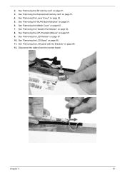
Remove the LCD with the brackets from the web camera. 12. 11. Remove the five screws (5 x B) securing the LCD module. Torque 3.0 kgf-cm Removing the Inverter Board and FPC Cable 1. Disconnect the cable from the back cover. Step 1~5 Size (Quantity) M2.5 x L6 (5) Color Black 13. See "Removing the Battery Pack" on page 50. 90 Chapter 3
Remove the LCD with the brackets from the web camera. 12. 11. Remove the five screws (5 x B) securing the LCD module. Torque 3.0 kgf-cm Removing the Inverter Board and FPC Cable 1. Disconnect the cable from the back cover. Step 1~5 Size (Quantity) M2.5 x L6 (5) Color Black 13. See "Removing the Battery Pack" on page 50. 90 Chapter 3
Aspire 5335 / 5735 / 5735Z Service Guide
Page 101
... "Removing the LCD panel with the Brackets" on page 88. 11. See "Removing the WLAN Board Modules" on page 51. 3. Disconnect the cables from the inverter board. 2. See "Removing the SD dummy card" on page 54. 6. See "Removing the Lower Cover" on page 65. 9. Chapter 3 91 See "Removing the CPU Heatsink...
... "Removing the LCD panel with the Brackets" on page 88. 11. See "Removing the WLAN Board Modules" on page 51. 3. Disconnect the cables from the inverter board. 2. See "Removing the SD dummy card" on page 54. 6. See "Removing the Lower Cover" on page 65. 9. Chapter 3 91 See "Removing the CPU Heatsink...
Aspire 5335 / 5735 / 5735Z Service Guide
Page 103
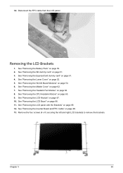
... and right LCD brackets to remove the brackets. See "Removing the Heatsink Fan Module" on page 90. 13. Removing the LCD Brackets 1. See "Removing the Inverter Board and FPC Cable" on page 64. 8. 14. See "Removing the ExpressCard dummy card" on page 62. 7. See "Removing the Middle Cover" on page 51...
... and right LCD brackets to remove the brackets. See "Removing the Heatsink Fan Module" on page 90. 13. Removing the LCD Brackets 1. See "Removing the Inverter Board and FPC Cable" on page 64. 8. 14. See "Removing the ExpressCard dummy card" on page 62. 7. See "Removing the Middle Cover" on page 51...
Aspire 5335 / 5735 / 5735Z Service Guide
Page 115
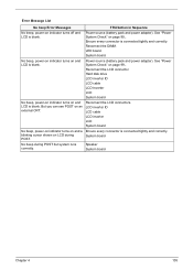
...shown on LCD during POST but system runs correctly. System board No beep during POST. Speaker System board Chapter 4 105 System board. LCD inverter ID LCD cable LCD inverter LCD System board No beep, power-on indicator turns on and a Ensure every connector is blank. No beep, power-on indicator turns ...on and LCD is connected tightly and correctly. Reconnect the LCD connector Hard disk drive LCD inverter ID LCD cable LCD Inverter LCD System board No beep, power-on indicator turns on and LCD is blank. But you can see POST on page 99.. ...
...shown on LCD during POST but system runs correctly. System board No beep during POST. Speaker System board Chapter 4 105 System board. LCD inverter ID LCD cable LCD inverter LCD System board No beep, power-on indicator turns on and a Ensure every connector is blank. No beep, power-on indicator turns ...on and LCD is connected tightly and correctly. Reconnect the LCD connector Hard disk drive LCD inverter ID LCD cable LCD Inverter LCD System board No beep, power-on indicator turns on and LCD is blank. But you can see POST on page 99.. ...
Aspire 5335 / 5735 / 5735Z Service Guide
Page 121
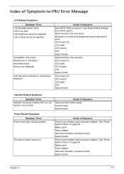
...is too dark LCD brightness cannot be adjusted LCD contrast cannot be adjusted Unreadable LCD screen Missing pels in Sequence Reconnect the inverter board Inverter board System board Power-Related Symptoms Symptom / Error Power shuts down during operation The system doesn't power-on page 99....board System board Chapter 4 111 Reconnect the LCD connectors. LCD inverter ID LCD cable LCD inverter LCD System board Reconnect the LCD connector LCD inverter ID LCD cable LCD inverter LCD System board LCD inverter ID LCD inverter LCD cable LCD System board Indicator-Related Symptoms Symptom / Error ...
...is too dark LCD brightness cannot be adjusted LCD contrast cannot be adjusted Unreadable LCD screen Missing pels in Sequence Reconnect the inverter board Inverter board System board Power-Related Symptoms Symptom / Error Power shuts down during operation The system doesn't power-on page 99....board System board Chapter 4 111 Reconnect the LCD connectors. LCD inverter ID LCD cable LCD inverter LCD System board Reconnect the LCD connector LCD inverter ID LCD cable LCD inverter LCD System board LCD inverter ID LCD inverter LCD cable LCD System board Indicator-Related Symptoms Symptom / Error ...
Aspire 5335 / 5735 / 5735Z Service Guide
Page 141
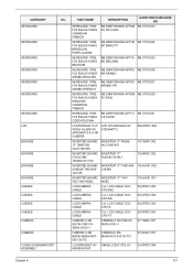
...CCD CP2 HL 50.ATR01.003 LCD/CAMERA CABLE C.A. YEC YNV-W06C W06C 19.AUA01.001 LCD/CAMERA CABLE C.A. PART NAME DESCRIPTION ACER OEM PURCHASE NO KEYBOARD 17KBFV5 BLACK 106KS CANADIAN FRENCH KB DARFON NSK-AFF0M KB.I1700.033 FC FR-CANA KEYBOARD 17KBFV5 BLACK 106KS ...DARFON VK.21189.407 VK.21189.408 19.TQ901.002 INVERTER BOARD INVERTER 17" FOXCONN T62I240.03 06L1 T62I240.03 V.00 19.AR501.002 INVERTER BOARD INVERTER 17" TWS-458- 19.AUA01.002 SUMIDA TWS-458- 124 MS 124 MS INVERTER BOARD INVERTER 17" YNV- CATEGORY KEYBOARD KEYBOARD KEYBOARD KEYBOARD KEYBOARD KEYBOARD...
...CCD CP2 HL 50.ATR01.003 LCD/CAMERA CABLE C.A. YEC YNV-W06C W06C 19.AUA01.001 LCD/CAMERA CABLE C.A. PART NAME DESCRIPTION ACER OEM PURCHASE NO KEYBOARD 17KBFV5 BLACK 106KS CANADIAN FRENCH KB DARFON NSK-AFF0M KB.I1700.033 FC FR-CANA KEYBOARD 17KBFV5 BLACK 106KS ...DARFON VK.21189.407 VK.21189.408 19.TQ901.002 INVERTER BOARD INVERTER 17" FOXCONN T62I240.03 06L1 T62I240.03 V.00 19.AR501.002 INVERTER BOARD INVERTER 17" TWS-458- 19.AUA01.002 SUMIDA TWS-458- 124 MS 124 MS INVERTER BOARD INVERTER 17" YNV- CATEGORY KEYBOARD KEYBOARD KEYBOARD KEYBOARD KEYBOARD KEYBOARD...

Aspire 5335 / 5735 / 5735Z Service Guide
Page 142
...OV772 CAMERA 0.3M BN30V4O7-030 OV772 57.AU401.001 132 Chapter 6 LCD CABLE CCD CP2 HL 50.ATR01.003 LCD/CAMERA CABLE C.A. PART NAME DESCRIPTION ACER OEM PURCHASE NO LCD BRACKET W/ HINGE LCD R CP2 SZS 33.ATR01.004 HINGE RIGHT LCD BRACKET W/ HINGE LCD L CP2 LH HINGE LEFT 33...*3 & 0.3M CAMERA LCD N15.6WXGAG W/ CCD&ANT*3 6M.ATR01.003 INVERTER BOARD INVERTER 17" ROHS 17" DARFON VK.21189.407 VK.21189.408 19.TQ901.002 INVERTER BOARD INVERTER 17" FOXCONN T62I240.03 06L1 T62I240.03 V.00 19.AR501.002 INVERTER BOARD INVERTER 17" TWS-458- 19.AUA01.002 SUMIDA TWS-458- 124 MS 124...
...OV772 CAMERA 0.3M BN30V4O7-030 OV772 57.AU401.001 132 Chapter 6 LCD CABLE CCD CP2 HL 50.ATR01.003 LCD/CAMERA CABLE C.A. PART NAME DESCRIPTION ACER OEM PURCHASE NO LCD BRACKET W/ HINGE LCD R CP2 SZS 33.ATR01.004 HINGE RIGHT LCD BRACKET W/ HINGE LCD L CP2 LH HINGE LEFT 33...*3 & 0.3M CAMERA LCD N15.6WXGAG W/ CCD&ANT*3 6M.ATR01.003 INVERTER BOARD INVERTER 17" ROHS 17" DARFON VK.21189.407 VK.21189.408 19.TQ901.002 INVERTER BOARD INVERTER 17" FOXCONN T62I240.03 06L1 T62I240.03 V.00 19.AR501.002 INVERTER BOARD INVERTER 17" TWS-458- 19.AUA01.002 SUMIDA TWS-458- 124 MS 124...


