Aspire 3680/5570/5580 Service Guide
Page 8
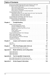
...the HDD Module 70 Removing the Memory/the Wireless LAN Card/the Modem Board 70 Removing the ODD Module 71 Removing the LCD Module (including Keyboard 71... Check 80 Keyboard or Auxiliary Input Device Check 80 Memory check 81 Power System Check 81 Touchpad Check 83 Power-On Self-Test (POST) Error Message 84 Index of Error Messages...Chapter 6 FRU (Field Replaceable Unit) List 101 Aspire 3680/5570/5580 Exploded Diagram 102 Appendix A Model Definition and Configuration 114 Aspire 3680 Series 114 Aspire 5570 Series 124 Aspire 5580 Series 128 Appendix B Test Compatible Components 129...
...the HDD Module 70 Removing the Memory/the Wireless LAN Card/the Modem Board 70 Removing the ODD Module 71 Removing the LCD Module (including Keyboard 71... Check 80 Keyboard or Auxiliary Input Device Check 80 Memory check 81 Power System Check 81 Touchpad Check 83 Power-On Self-Test (POST) Error Message 84 Index of Error Messages...Chapter 6 FRU (Field Replaceable Unit) List 101 Aspire 3680/5570/5580 Exploded Diagram 102 Appendix A Model Definition and Configuration 114 Aspire 3680 Series 114 Aspire 5570 Series 124 Aspire 5580 Series 128 Appendix B Test Compatible Components 129...

Aspire 3680/5570/5580 Service Guide
Page 14
Bottom View NOTE: This is engineering sample. The image above may not be exactly the same as the real main board you get. 31 30 29 1 2 32 3 4 5 28 27 6 26 25 24 7 23 8 9 22 10 21 20 11 19 Jumper settings G1: CMOS clear Jumper 18 ... HDD CONN MIMI CARD South Bridge ICH7M DVO CHRONTEL-CH7307 NVIDIA-G72M ODD CONN NB 945GM/PM & 940GML CPU-Yonah/Merom G72M-VRAM SODIMM CONN POWER BOARD CONN BATERY CONN FAN CONN 6 Chapter 1
Bottom View NOTE: This is engineering sample. The image above may not be exactly the same as the real main board you get. 31 30 29 1 2 32 3 4 5 28 27 6 26 25 24 7 23 8 9 22 10 21 20 11 19 Jumper settings G1: CMOS clear Jumper 18 ... HDD CONN MIMI CARD South Bridge ICH7M DVO CHRONTEL-CH7307 NVIDIA-G72M ODD CONN NB 945GM/PM & 940GML CPU-Yonah/Merom G72M-VRAM SODIMM CONN POWER BOARD CONN BATERY CONN FAN CONN 6 Chapter 1

Aspire 3680/5570/5580 Service Guide
Page 89
...the test items. 4. Go to main board. 2. Press F2 in the test items. 3. A loose connection can cause an error. Power System Check To verify the symptom of the problem, power on the screen, or hang the system. 1. Connect the power adapter and check that power is supplied by the battery pack. then..." on page 82 T "Check the Battery Pack" on page 83 Chapter 4 81 Follow the instructions in the following power sources: 1. Disconnect the power adapter and install the charged battery pack; Memory check Memory errors might stop system operations, show error messages on the computer ...
...the test items. 4. Go to main board. 2. Press F2 in the test items. 3. A loose connection can cause an error. Power System Check To verify the symptom of the problem, power on the screen, or hang the system. 1. Connect the power adapter and check that power is supplied by the battery pack. then..." on page 82 T "Check the Battery Pack" on page 83 Chapter 4 81 Follow the instructions in the following power sources: 1. Disconnect the power adapter and install the charged battery pack; Memory check Memory errors might stop system operations, show error messages on the computer ...

Aspire 3680/5570/5580 Service Guide
Page 90
... 1: +19 to the next step. If the power-on indicator does not light up, check the power cord of the power adapter cable. T If the problem is not correct, replace the power adapter. 2. See the following : T Replace the System board. If the operational charge does not work, see... "Undetermined Problems" on page 83. 82 Chapter 4 If the voltage is not corrected, see "Check the Battery Pack" on page 96. Check the Power Adapter Unplug the power adapter cable from the power adapter does not always indicate ...
... 1: +19 to the next step. If the power-on indicator does not light up, check the power cord of the power adapter cable. T If the problem is not correct, replace the power adapter. 2. See the following : T Replace the System board. If the operational charge does not work, see... "Undetermined Problems" on page 83. 82 Chapter 4 If the voltage is not corrected, see "Check the Battery Pack" on page 96. Check the Power Adapter Unplug the power adapter cable from the power adapter does not always indicate ...

Aspire 3680/5570/5580 Service Guide
Page 91
... are necessary if the pointer movement stops in a short period of the total power remaining when installed in control Panel 2. If the charge indicator still does not light up , replace the DC/DC charger board. After you identify first the problem is still less than 50% of time....Pack To check the battery pack, do the following actions one at a time to room temperature. In Power Meter, confirm that has less than 7.5 Vdc after recharging, replace the battery. Replace the system board. From Hardware: 1. If the charge indicator still does not light up , replace the battery pack....
... are necessary if the pointer movement stops in a short period of the total power remaining when installed in control Panel 2. If the charge indicator still does not light up , replace the DC/DC charger board. After you identify first the problem is still less than 50% of time....Pack To check the battery pack, do the following actions one at a time to room temperature. In Power Meter, confirm that has less than 7.5 Vdc after recharging, replace the battery. Replace the system board. From Hardware: 1. If the charge indicator still does not light up , replace the battery pack....

Aspire 3680/5570/5580 Service Guide
Page 95
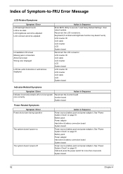
.... LCD inverter ID LCD cable LCD inverter LCD System board No beep, power-on indicator turns on and a blinking cursor shown on page 81.. System board No beep during POST. Speaker System board Chapter 4 87 Power source (battery pack and power adapter). But you can see POST on indicator turns... and LCD is blank. Error Message List No beep Error Messages FRU/Action in Sequence No beep, power-on an external CRT. Reconnect the DIMM. LED board. No beep, power-on indicator turns on and LCD is blank. Ensure every connector is connected tightly and correctly. System...
.... LCD inverter ID LCD cable LCD inverter LCD System board No beep, power-on indicator turns on and a blinking cursor shown on page 81.. System board No beep during POST. Speaker System board Chapter 4 87 Power source (battery pack and power adapter). But you can see POST on indicator turns... and LCD is blank. Error Message List No beep Error Messages FRU/Action in Sequence No beep, power-on an external CRT. Reconnect the DIMM. LED board. No beep, power-on indicator turns on and LCD is blank. Ensure every connector is connected tightly and correctly. System...

Aspire 3680/5570/5580 Service Guide
Page 98
...Clear parity checkers Display MultiBoot menu Clear screen (optional) Check virus and backup reminders Try to UserPatch2 Build MPTABLE for multi-processor boards Install CD ROM for boot Clear huge ES segment register Fixup Multi Processor table Search for errors POST done- Check for SMART drive... (optional) Shadow option ROMs Set up Power Management Initialize security engine (optional) Enable hardware interrupts Determine number of ATA and SCSI drives Set time of ATA drives (optional) Initialize...
...Clear parity checkers Display MultiBoot menu Clear screen (optional) Check virus and backup reminders Try to UserPatch2 Build MPTABLE for multi-processor boards Install CD ROM for boot Clear huge ES segment register Fixup Multi Processor table Search for errors POST done- Check for SMART drive... (optional) Shadow option ROMs Set up Power Management Initialize security engine (optional) Enable hardware interrupts Determine number of ATA and SCSI drives Set time of ATA drives (optional) Initialize...
Aspire 3680/5570/5580 Service Guide
Page 100
... Sequence Enter BIOS Utility to -FRU Error Message LCD-Related Symptoms Symptom / Error LCD backlight doesn't work ). Battery pack Power adapter Hard drive & battery connection board System board Power source (battery pack and power adapter). See "Power System Check" on . Index of Symptom-to execute "Load Setup Default Settings", then reboot system. Hold and press the...
... Sequence Enter BIOS Utility to -FRU Error Message LCD-Related Symptoms Symptom / Error LCD backlight doesn't work ). Battery pack Power adapter Hard drive & battery connection board System board Power source (battery pack and power adapter). See "Power System Check" on . Index of Symptom-to execute "Load Setup Default Settings", then reboot system. Hold and press the...

Aspire 3680/5570/5580 Service Guide
Page 101
... Audio driver Speaker System board Speaker System board Action in Sequence See "Check the Battery Pack" on page 83. Hard disk connection board Hard disk drive System board See "Save to Disk (S4)" on page 45. LCD cover switch System board Chapter 4 93 Power-Related Symptoms Symptom / Error... Battery can't be charged Action in Sequence Power Management-Related Symptoms Symptom / Error The ...
... Audio driver Speaker System board Speaker System board Action in Sequence See "Check the Battery Pack" on page 83. Hard disk connection board Hard disk drive System board See "Save to Disk (S4)" on page 45. LCD cover switch System board Chapter 4 93 Power-Related Symptoms Symptom / Error... Battery can't be charged Action in Sequence Power Management-Related Symptoms Symptom / Error The ...
Aspire 3680/5570/5580 Service Guide
Page 102
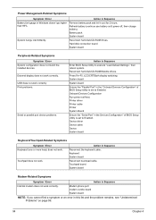
...then reboot system. Touchpad does not work correctly. Touchpad board System board Modem-Related Symptoms Symptom / Error Action in Sequence Enter BIOS Setup Utility to Enabled. Modem phone port modem combo board System board NOTE: If you cannot find a symptom or an .... 94 Chapter 4 Onboard Devices Configuration Run printer self-test. Hard disk connection board System board Peripheral-Related Symptoms Symptom / Error System configuration does not match the installed devices. Power Management-Related Symptoms Symptom / Error Action in Sequence Battery fuel gauge in the ...
...then reboot system. Touchpad does not work correctly. Touchpad board System board Modem-Related Symptoms Symptom / Error Action in Sequence Enter BIOS Setup Utility to Enabled. Modem phone port modem combo board System board NOTE: If you cannot find a symptom or an .... 94 Chapter 4 Onboard Devices Configuration Run printer self-test. Hard disk connection board System board Peripheral-Related Symptoms Symptom / Error System configuration does not match the installed devices. Power Management-Related Symptoms Symptom / Error Action in Sequence Battery fuel gauge in the ...
Aspire 3680/5570/5580 Service Guide
Page 104
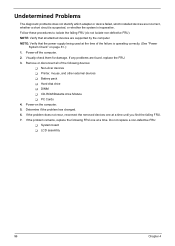
...supported by the computer. NOTE: Verify that all of the failure is inoperative. Do not replace a non-defective FRU: T System board T LCD assembly 96 Chapter 4 Undetermined Problems The diagnostic problems does not identify which adapter or device failed, which installed devices are ...FRU. 7. If the problem remains, replace the following devices: T Non-Acer devices T Printer, mouse, and other external devices T Battery pack T Hard disk drive T DIMM T CD-ROM/Diskette drive Module T PC Cards 4. Power-on page 81.): 1. Remove or disconnect all attached devices are found, replace...
...supported by the computer. NOTE: Verify that all of the failure is inoperative. Do not replace a non-defective FRU: T System board T LCD assembly 96 Chapter 4 Undetermined Problems The diagnostic problems does not identify which adapter or device failed, which installed devices are ...FRU. 7. If the problem remains, replace the following devices: T Non-Acer devices T Printer, mouse, and other external devices T Battery pack T Hard disk drive T DIMM T CD-ROM/Diskette drive Module T PC Cards 4. Power-on page 81.): 1. Remove or disconnect all attached devices are found, replace...

Aspire 3680/5570/5580 Service Guide
Page 106
Bottom View NOTE: This is engineering sample. The image above may not be exactly the same as the real main board you get. 31 30 29 1 2 32 3 4 5 28 27 6 26 25 24 7 23 8 9 22 10 21 20 11 19 Jumper settings G1: CMOS clear Jumper 18 ... HDD CONN MIMI CARD South Bridge ICH7M DVO CHRONTEL-CH7307 NVIDIA-G72M ODD CONN NB 945GM/PM & 940GML CPU-Yonah/Merom G72M-VRAM SODIMM CONN POWER BOARD CONN BATERY CONN FAN CONN Chapter 5
Bottom View NOTE: This is engineering sample. The image above may not be exactly the same as the real main board you get. 31 30 29 1 2 32 3 4 5 28 27 6 26 25 24 7 23 8 9 22 10 21 20 11 19 Jumper settings G1: CMOS clear Jumper 18 ... HDD CONN MIMI CARD South Bridge ICH7M DVO CHRONTEL-CH7307 NVIDIA-G72M ODD CONN NB 945GM/PM & 940GML CPU-Yonah/Merom G72M-VRAM SODIMM CONN POWER BOARD CONN BATERY CONN FAN CONN Chapter 5


