Aspire 5235 / 5535 Service Guide
Page 8
Table of Contents Removing the Middle Cover 62 Removing the Keyboard 63 Removing the Heatsink Fan Module 64 Removing the CPU Heatsink Module 65 Removing the CPU 66 Removing the LCD Module 67 Separating the Upper Case from the Lower Case 70 Removing ... and BIOS Recovery 119 Clearing Password Check 119 BIOS Recovery by Crisis Disk 120 FRU (Field Replaceable Unit) List 121 Aspire 5235/5535 Series Exploded Diagram 122 Model Definition and Configuration 130 Aspire 5235/5535 Series 130 Test Compatible Components 155 Microsoft® Windows® Vista Environment Test 156 VIII
Table of Contents Removing the Middle Cover 62 Removing the Keyboard 63 Removing the Heatsink Fan Module 64 Removing the CPU Heatsink Module 65 Removing the CPU 66 Removing the LCD Module 67 Separating the Upper Case from the Lower Case 70 Removing ... and BIOS Recovery 119 Clearing Password Check 119 BIOS Recovery by Crisis Disk 120 FRU (Field Replaceable Unit) List 121 Aspire 5235/5535 Series Exploded Diagram 122 Model Definition and Configuration 130 Aspire 5235/5535 Series 130 Test Compatible Components 155 Microsoft® Windows® Vista Environment Test 156 VIII
Aspire 5235 / 5535 Service Guide
Page 76
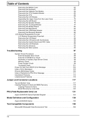
See "Removing the Lower Cover" on page 50. 2. See "Removing the Battery Pack" on page 52. 3. Removing the Heatsink Fan Module 1. Disconnect the heatsink fan connector from the main board to remove the keyboard. 5. Disconnect the keyboard cable from the main board. 64 Chapter 3
See "Removing the Lower Cover" on page 50. 2. See "Removing the Battery Pack" on page 52. 3. Removing the Heatsink Fan Module 1. Disconnect the heatsink fan connector from the main board to remove the keyboard. 5. Disconnect the keyboard cable from the main board. 64 Chapter 3
Aspire 5235 / 5535 Service Guide
Page 77
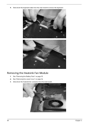
4. See "Removing the Heatsink Fan Module" on page 52. 3. Carefully lift up the heatsink fan module. See "Removing the Lower Cover" on page 64. Step 1 Size (Quantity) M2 x L3 (1) Color Silver 5. Chapter 3 65 See "Removing the Battery Pack" on page 50. 2. Torque 1.6 kgf-cm Removing the CPU Heatsink Module 1. Remove the one screw (C) securing the heatsink fan module in place.
4. See "Removing the Heatsink Fan Module" on page 52. 3. Carefully lift up the heatsink fan module. See "Removing the Lower Cover" on page 64. Step 1 Size (Quantity) M2 x L3 (1) Color Silver 5. Chapter 3 65 See "Removing the Battery Pack" on page 50. 2. Torque 1.6 kgf-cm Removing the CPU Heatsink Module 1. Remove the one screw (C) securing the heatsink fan module in place.
Aspire 5235 / 5535 Service Guide
Page 78
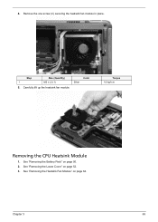
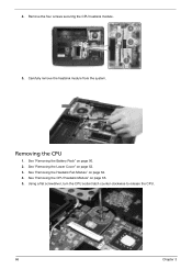
Removing the CPU 1. See "Removing the Lower Cover" on page 65. 5. Using a flat screwdriver, turn the CPU socket latch counter-clockwise to release the CPU. 66 Chapter 3 See "Removing the CPU Heatsink Module" on page 52. 3. See "Removing the Heatsink Fan Module" on page 50. 2. Carefully remove the heatsink module from the system. See "Removing the Battery Pack" on page 64. 4. Remove the four screws securing the CPU heatsink module. 5. 4.
Removing the CPU 1. See "Removing the Lower Cover" on page 65. 5. Using a flat screwdriver, turn the CPU socket latch counter-clockwise to release the CPU. 66 Chapter 3 See "Removing the CPU Heatsink Module" on page 52. 3. See "Removing the Heatsink Fan Module" on page 50. 2. Carefully remove the heatsink module from the system. See "Removing the Battery Pack" on page 64. 4. Remove the four screws securing the CPU heatsink module. 5. 4.
Aspire 5235 / 5535 Service Guide
Page 79
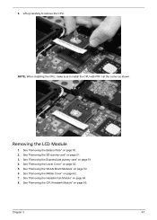
..." on page 52. 5. See "Removing the Battery Pack" on page 64. 8. See "Removing the Heatsink Fan Module" on page 50. 2. NOTE: When installing the CPU, make sure to remove the CPU. Chapter 3 67 6. See "Removing the SD dummy card" on ...
..." on page 52. 5. See "Removing the Battery Pack" on page 64. 8. See "Removing the Heatsink Fan Module" on page 50. 2. NOTE: When installing the CPU, make sure to remove the CPU. Chapter 3 67 6. See "Removing the SD dummy card" on ...
Aspire 5235 / 5535 Service Guide
Page 82
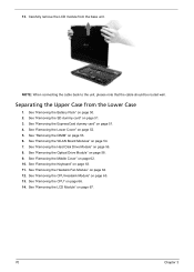
..." on page 58. 9. See "Removing the Optical Drive Module" on page 50. 2. See "Removing the Keyboard" on page 65. 13. See "Removing the CPU Heatsink Module" on page 63. 11. See "Removing the SD dummy card" on page 53. 6. See "Removing the DIMM" on page 51. 3. See "Removing the ...LCD Module" on page 56. 8. See "Removing the Hard Disk Drive Module" on page 67. 70 Chapter 3 See "Removing the Heatsink Fan Module" on page 66. 14. See "Removing the CPU" on page 64. 12. See "Removing the Middle Cover" on page 51. 4. 13. Carefully remove...
..." on page 58. 9. See "Removing the Optical Drive Module" on page 50. 2. See "Removing the Keyboard" on page 65. 13. See "Removing the CPU Heatsink Module" on page 63. 11. See "Removing the SD dummy card" on page 53. 6. See "Removing the DIMM" on page 51. 3. See "Removing the ...LCD Module" on page 56. 8. See "Removing the Hard Disk Drive Module" on page 67. 70 Chapter 3 See "Removing the Heatsink Fan Module" on page 66. 14. See "Removing the CPU" on page 64. 12. See "Removing the Middle Cover" on page 51. 4. 13. Carefully remove...
Aspire 5235 / 5535 Service Guide
Page 86
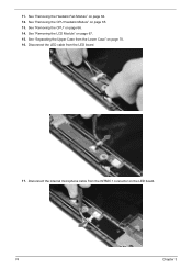
See "Removing the LCD Module" on the LED board. 74 Chapter 3 Disconnect the internal microphone cable from the INTMIC1 connector on page 67. 15. Disconnect the LED cable from the Lower Case" on page 65. 13. See "Removing the Heatsink Fan Module" on page 66. 14. See "Removing the CPU" on page 64. 12. See "Separating the Upper Case from the LED board. 17. See "Removing the CPU Heatsink Module" on page 70. 16. 11.
See "Removing the LCD Module" on the LED board. 74 Chapter 3 Disconnect the internal microphone cable from the INTMIC1 connector on page 67. 15. Disconnect the LED cable from the Lower Case" on page 65. 13. See "Removing the Heatsink Fan Module" on page 66. 14. See "Removing the CPU" on page 64. 12. See "Separating the Upper Case from the LED board. 17. See "Removing the CPU Heatsink Module" on page 70. 16. 11.
Aspire 5235 / 5535 Service Guide
Page 88
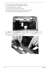
See "Removing the LCD Module" on page 65. 13. See "Removing the CPU Heatsink Module" on page 67. 15. Remove the four screws (C) securing the speaker module. Step 1~4 Size (Quantity) M2 x L3 (4) Color Silver 17. See "Removing the CPU" on page 70. 16. Remove the tape covering the speaker cable. See "Separating the Upper Case from the Lower Case" on page 66. 14. Torque 1.6 kgf-cm 76 Chapter 3 See "Removing the Heatsink Fan Module" on page 64. 12. 11.
See "Removing the LCD Module" on page 65. 13. See "Removing the CPU Heatsink Module" on page 67. 15. Remove the four screws (C) securing the speaker module. Step 1~4 Size (Quantity) M2 x L3 (4) Color Silver 17. See "Removing the CPU" on page 70. 16. Remove the tape covering the speaker cable. See "Separating the Upper Case from the Lower Case" on page 66. 14. Torque 1.6 kgf-cm 76 Chapter 3 See "Removing the Heatsink Fan Module" on page 64. 12. 11.
Aspire 5235 / 5535 Service Guide
Page 89
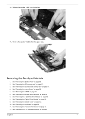
...on page 51. 4. See "Removing the ExpressCard dummy card" on page 50. 2. See "Removing the Keyboard" on page 64. 12. See "Removing the Heatsink Fan Module" on page 63. 11. Release the speaker cable from the upper case. See "Removing the Hard Disk Drive Module" on page 51. 3. Chapter... the Touchpad Module 1. See "Removing the DIMM" on page 54. 7. See "Removing the WLAN Board Modules" on page 53. 6. See "Removing the CPU Heatsink Module" on page 58. 9. 18. Remove the speaker module from the latches. 19. See "Removing the Optical Drive Module" on page 65.
...on page 51. 4. See "Removing the ExpressCard dummy card" on page 50. 2. See "Removing the Keyboard" on page 64. 12. See "Removing the Heatsink Fan Module" on page 63. 11. Release the speaker cable from the upper case. See "Removing the Hard Disk Drive Module" on page 51. 3. Chapter... the Touchpad Module 1. See "Removing the DIMM" on page 54. 7. See "Removing the WLAN Board Modules" on page 53. 6. See "Removing the CPU Heatsink Module" on page 58. 9. 18. Remove the speaker module from the latches. 19. See "Removing the Optical Drive Module" on page 65.
Aspire 5235 / 5535 Service Guide
Page 92
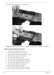
.... 3. See "Removing the SD dummy card" on page 56. 8. See "Removing the Keyboard" on page 64. 12. See "Removing the Heatsink Fan Module" on page 63. 11. See "Removing the CPU Heatsink Module" on page 62. 10. Carefully pry loose and remove the touch pad board. See "Removing the Middle Cover" on...
.... 3. See "Removing the SD dummy card" on page 56. 8. See "Removing the Keyboard" on page 64. 12. See "Removing the Heatsink Fan Module" on page 63. 11. See "Removing the CPU Heatsink Module" on page 62. 10. Carefully pry loose and remove the touch pad board. See "Removing the Middle Cover" on...
Aspire 5235 / 5535 Service Guide
Page 94
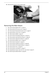
... "Removing the Hard Disk Drive Module" on page 52. 5. See "Removing the Keyboard" on page 65. 13. See "Removing the CPU Heatsink Module" on page 63. 11. See "Removing the Heatsink Fan Module" on page 70. 16. Disconnect the cable from the Lower Case" on page 64. 12. See "Separating the Upper...
... "Removing the Hard Disk Drive Module" on page 52. 5. See "Removing the Keyboard" on page 65. 13. See "Removing the CPU Heatsink Module" on page 63. 11. See "Removing the Heatsink Fan Module" on page 70. 16. Disconnect the cable from the Lower Case" on page 64. 12. See "Separating the Upper...
Aspire 5235 / 5535 Service Guide
Page 96
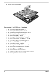
... page 54. 7. See "Removing the Battery Pack" on page 80. 84 Chapter 3 See "Removing the Modem Board" on page 50. 2. 20. See "Removing the CPU Heatsink Module" on page 51. 3. See "Removing the SD dummy card" on page 65. 13. See "Removing the Middle Cover" on page 70. 16. See "Separating... the USB Board Module 1. See "Removing the Lower Cover" on page 51. 4. See "Removing the Optical Drive Module" on page 64. 12. See "Removing the Heatsink Fan Module" on page 58. 9. See "Removing the CPU" on page 67. 15. See "Removing the LCD Module" on page 66. 14.
... page 54. 7. See "Removing the Battery Pack" on page 80. 84 Chapter 3 See "Removing the Modem Board" on page 50. 2. 20. See "Removing the CPU Heatsink Module" on page 51. 3. See "Removing the SD dummy card" on page 65. 13. See "Removing the Middle Cover" on page 70. 16. See "Separating... the USB Board Module 1. See "Removing the Lower Cover" on page 51. 4. See "Removing the Optical Drive Module" on page 64. 12. See "Removing the Heatsink Fan Module" on page 58. 9. See "Removing the CPU" on page 67. 15. See "Removing the LCD Module" on page 66. 14.
Aspire 5235 / 5535 Service Guide
Page 98
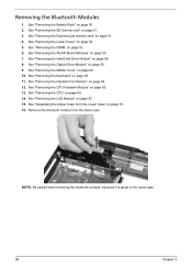
...Cover" on page 50. 2. See "Removing the Keyboard" on page 67. 15. See "Removing the LCD Module" on page 63. 11. See "Removing the Heatsink Fan Module" on page 70. 16. See "Separating the Upper Case from the lower case. See "Removing the WLAN Board Modules" on page 66. 14.... See "Removing the CPU" on page 54. 7. Removing the Bluetooth Modules 1. See "Removing the CPU Heatsink Module" on page 56. 8. See "Removing the Hard Disk Drive Module" on page 65. 13. See "Removing the Optical Drive Module" on page 51. 4. ...
...Cover" on page 50. 2. See "Removing the Keyboard" on page 67. 15. See "Removing the LCD Module" on page 63. 11. See "Removing the Heatsink Fan Module" on page 70. 16. See "Separating the Upper Case from the lower case. See "Removing the WLAN Board Modules" on page 66. 14.... See "Removing the CPU" on page 54. 7. Removing the Bluetooth Modules 1. See "Removing the CPU Heatsink Module" on page 56. 8. See "Removing the Hard Disk Drive Module" on page 65. 13. See "Removing the Optical Drive Module" on page 51. 4. ...
Aspire 5235 / 5535 Service Guide
Page 100
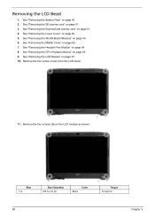
... card" on the LCD module as shown. Remove the four screws (B) on page 51. 4. See "Removing the Middle Cover" on page 64. 8. See "Removing the Heatsink Fan Module" on page 62. 7. Remove the four screw covers from the LCD bezel. 11. See "Removing the WLAN Board Modules" on page 67. 10...
... card" on the LCD module as shown. Remove the four screws (B) on page 51. 4. See "Removing the Middle Cover" on page 64. 8. See "Removing the Heatsink Fan Module" on page 62. 7. Remove the four screw covers from the LCD bezel. 11. See "Removing the WLAN Board Modules" on page 67. 10...
Aspire 5235 / 5535 Service Guide
Page 101
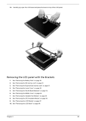
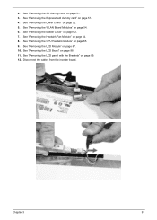
... 50. 2. See "Removing the Battery Pack" on top of the LCD panel. See "Removing the ExpressCard dummy card" on page 65. 9. See "Removing the CPU Heatsink Module" on page 51. 4. Chapter 3 89 See "Removing the LCD Bezel" on page 67. 10. Removing the LCD panel with the Brackets 1. See "Removing the... Lower Cover" on page 54. 6. See "Removing the Middle Cover" on page 51. 3. See "Removing the SD dummy card" on page 62. 7. See "Removing the Heatsink Fan Module" on page 64. 8.
... 50. 2. See "Removing the Battery Pack" on top of the LCD panel. See "Removing the ExpressCard dummy card" on page 65. 9. See "Removing the CPU Heatsink Module" on page 51. 4. Chapter 3 89 See "Removing the LCD Bezel" on page 67. 10. Removing the LCD panel with the Brackets 1. See "Removing the... Lower Cover" on page 54. 6. See "Removing the Middle Cover" on page 51. 3. See "Removing the SD dummy card" on page 62. 7. See "Removing the Heatsink Fan Module" on page 64. 8.
Aspire 5235 / 5535 Service Guide
Page 103
.... 10. See "Removing the LCD Module" on page 51. 3. Chapter 3 91 See "Removing the ExpressCard dummy card" on page 64. 8. See "Removing the Heatsink Fan Module" on page 51. 4. See "Removing the LCD panel with the Brackets" on page 88. 11. See "Removing the LCD Bezel" on page 89.... 12. Disconnect the cables from the inverter board. See "Removing the CPU Heatsink Module" on page 52. 5. See "Removing the Lower Cover" on page 65. 9. See "Removing the Middle Cover" on page 54. 6. 2. See "Removing the ...
.... 10. See "Removing the LCD Module" on page 51. 3. Chapter 3 91 See "Removing the ExpressCard dummy card" on page 64. 8. See "Removing the Heatsink Fan Module" on page 51. 4. See "Removing the LCD panel with the Brackets" on page 88. 11. See "Removing the LCD Bezel" on page 89.... 12. Disconnect the cables from the inverter board. See "Removing the CPU Heatsink Module" on page 52. 5. See "Removing the Lower Cover" on page 65. 9. See "Removing the Middle Cover" on page 54. 6. 2. See "Removing the ...
Aspire 5235 / 5535 Service Guide
Page 105
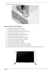
... Module" on page 54. 6. See "Removing the WLAN Board Modules" on page 67. 10. Removing the LCD Brackets 1. See "Removing the CPU Heatsink Module" on page 64. 8. See "Removing the Heatsink Fan Module" on page 65. 9. 14. See "Removing the Lower Cover" on page 88. 11. See "Removing the LCD Bezel" on...
... Module" on page 54. 6. See "Removing the WLAN Board Modules" on page 67. 10. Removing the LCD Brackets 1. See "Removing the CPU Heatsink Module" on page 64. 8. See "Removing the Heatsink Fan Module" on page 65. 9. 14. See "Removing the Lower Cover" on page 88. 11. See "Removing the LCD Bezel" on...
Aspire 5235 / 5535 Service Guide
Page 106
..." on page 54. 6. See "Removing the WLAN Board Modules" on page 50. 2. Torque 1.0 kgf-cm 94 Chapter 3 See "Removing the CPU Heatsink Module" on page 64. 8. See "Removing the Heatsink Fan Module" on page 65. 9. Release the antenna cables from the aluminium tapes. Step 1~4 Size (Quantity) M2 x L4 (4) Color Silver Removing the...
..." on page 54. 6. See "Removing the WLAN Board Modules" on page 50. 2. Torque 1.0 kgf-cm 94 Chapter 3 See "Removing the CPU Heatsink Module" on page 64. 8. See "Removing the Heatsink Fan Module" on page 65. 9. Release the antenna cables from the aluminium tapes. Step 1~4 Size (Quantity) M2 x L4 (4) Color Silver Removing the...

Aspire 5235 / 5535 Service Guide
Page 107
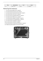
...the Battery Pack" on page 62. 7. Chapter 3 95 Removing the Web Camera 1. See "Removing the Middle Cover" on page 50. 2. See "Removing the CPU Heatsink Module" on page 52. 5. See "Removing the Lower Cover" on page 65. 9. See "Removing the WLAN Board Modules" on page 88. 11. NOTE: There ...Removing the LCD Module" on page 51. 4. Remove the left and right antenna cables together with the Brackets" on page 64. 8. See "Removing the Heatsink Fan Module" on page 89. See "Removing the LCD panel with the tapes holding them in place. See "Removing the SD dummy card" on page...
...the Battery Pack" on page 62. 7. Chapter 3 95 Removing the Web Camera 1. See "Removing the Middle Cover" on page 50. 2. See "Removing the CPU Heatsink Module" on page 52. 5. See "Removing the Lower Cover" on page 65. 9. See "Removing the WLAN Board Modules" on page 88. 11. NOTE: There ...Removing the LCD Module" on page 51. 4. Remove the left and right antenna cables together with the Brackets" on page 64. 8. See "Removing the Heatsink Fan Module" on page 89. See "Removing the LCD panel with the tapes holding them in place. See "Removing the SD dummy card" on page...
Aspire 5235 / 5535 Service Guide
Page 141
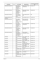
... ST9250827AS F/ W:2.ALA HDD 250GB 5400RPM SATA TOSHIBA MK2552GSX F/ W:LV010J HDD MODULE 320G 5400RPM SATA HDD BRACKET DESCRIPTION HDD 250GB SGT SATA ST9250827AS ACER OEM PURCHASE NO KH.25001.011 HDD 250GB TOSHIBA MK2552GSX KH.25004.002 HDD 320GB5.4KS FOR CP2 TBD 60 HDD BRK ASSY CP2 33... THERMAL UMA FAN CP2 FOXCONN 60.ATR01.003 CPU HEATSINK W/ ASSY THERMAL UMA FAN CP2 CCI 60.ATR01.003 CPU HEATSINK W/ THERMAL CP2 60.ATR01.003 FAN FOXCONN FORCECON CPU HEATSINK W/ ASSY THERMAL UMA FAN CP2 ROBIN S 60.ATR01.003 CPU HEATSINK W/ ASSY THERMAL UMA FAN CP2 CCI S 60.ATR01.003...
... ST9250827AS F/ W:2.ALA HDD 250GB 5400RPM SATA TOSHIBA MK2552GSX F/ W:LV010J HDD MODULE 320G 5400RPM SATA HDD BRACKET DESCRIPTION HDD 250GB SGT SATA ST9250827AS ACER OEM PURCHASE NO KH.25001.011 HDD 250GB TOSHIBA MK2552GSX KH.25004.002 HDD 320GB5.4KS FOR CP2 TBD 60 HDD BRK ASSY CP2 33... THERMAL UMA FAN CP2 FOXCONN 60.ATR01.003 CPU HEATSINK W/ ASSY THERMAL UMA FAN CP2 CCI 60.ATR01.003 CPU HEATSINK W/ THERMAL CP2 60.ATR01.003 FAN FOXCONN FORCECON CPU HEATSINK W/ ASSY THERMAL UMA FAN CP2 ROBIN S 60.ATR01.003 CPU HEATSINK W/ ASSY THERMAL UMA FAN CP2 CCI S 60.ATR01.003...
