Acer Aspire User's Guide
Page 7
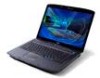
... shielded from your device in health care facilities when any regulations posted in its use is completed. These recommendations are not limited to: wireless lan (WLAN), Bluetooth and/or 3G. vii Additional safety information Your device and its enhancements may be attracted to the device, and persons with hearing aids should...
... shielded from your device in health care facilities when any regulations posted in its use is completed. These recommendations are not limited to: wireless lan (WLAN), Bluetooth and/or 3G. vii Additional safety information Your device and its enhancements may be attracted to the device, and persons with hearing aids should...
Acer Aspire User's Guide
Page 36
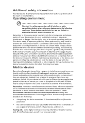
... utility (only for certain models). The mail and Web browser buttons are : WLAN, Internet, email, Bluetooth, Arcade and Acer Empowering Technology. Icon Function Description Wireless communication button/indicator (manufacturing option) Enables/disables ... Email application (user-Programmable) Bluetooth communication button/ indicator (manufacturing option) Arcade Enables/disables the Bluetooth function. Acer Empowering Technology Launch Acer Empowering Technology (user-programmable) To set to start the application. Indicates the status of wireless LAN communication. They...
... utility (only for certain models). The mail and Web browser buttons are : WLAN, Internet, email, Bluetooth, Arcade and Acer Empowering Technology. Icon Function Description Wireless communication button/indicator (manufacturing option) Enables/disables ... Email application (user-Programmable) Bluetooth communication button/ indicator (manufacturing option) Arcade Enables/disables the Bluetooth function. Acer Empowering Technology Launch Acer Empowering Technology (user-programmable) To set to start the application. Indicates the status of wireless LAN communication. They...
Service Guide
Page 7
Table of Contents System Specifications 1 Features 1 System Block Diagram 4 Your Acer Notebook tour 5 Front View 5 Closed Front View 6 Left View 7 Right View 8 Rear View 8...and embedded numeric keypad 12 Windows Keys 13 Hot Keys 14 Special Key 15 Using the System Utilities 16 Acer GridVista (dual-display compatible 16 Hardware Specifications and Configurations 18 System Utilities 27 BIOS Setup Utility 27 Navigating... the Lower Covers 53 Removing the DIMM Modules 55 Removing the WLAN Module 56 Removing the TV tuner Module 58 Removing the Hard Disk Drive Module 60 VII
Table of Contents System Specifications 1 Features 1 System Block Diagram 4 Your Acer Notebook tour 5 Front View 5 Closed Front View 6 Left View 7 Right View 8 Rear View 8...and embedded numeric keypad 12 Windows Keys 13 Hot Keys 14 Special Key 15 Using the System Utilities 16 Acer GridVista (dual-display compatible 16 Hardware Specifications and Configurations 18 System Utilities 27 BIOS Setup Utility 27 Navigating... the Lower Covers 53 Removing the DIMM Modules 55 Removing the WLAN Module 56 Removing the TV tuner Module 58 Removing the Hard Disk Drive Module 60 VII
Service Guide
Page 9
... LCD Module 131 Replacing the Antenna Cables 133 Replacing the Keyboard 134 Replacing the Switch Cover 134 Replacing the TV Tuner Module 135 Replacing the WLAN Module 137 Replacing the Hard Disk Drive Module 137 Replacing the DIMM Modules 138 Replacing the ODD Module 139 Replacing the Lower Covers 140 Replacing... View 166 Clearing Password Check and BIOS Recovery 167 Clearing Password Check 167 BIOS Recovery by Crisis Disk 168 FRU (Field Replaceable Unit) List 171 Aspire 5530 Exploded Diagrams 172 Discrete SKU 172 UMA SKU 173 IX
... LCD Module 131 Replacing the Antenna Cables 133 Replacing the Keyboard 134 Replacing the Switch Cover 134 Replacing the TV Tuner Module 135 Replacing the WLAN Module 137 Replacing the Hard Disk Drive Module 137 Replacing the DIMM Modules 138 Replacing the ODD Module 139 Replacing the Lower Covers 140 Replacing... View 166 Clearing Password Check and BIOS Recovery 167 Clearing Password Check 167 BIOS Recovery by Crisis Disk 168 FRU (Field Replaceable Unit) List 171 Aspire 5530 Exploded Diagrams 172 Discrete SKU 172 UMA SKU 173 IX
Service Guide
Page 12
...-definition audio support MS-Sound compatible Built-in microphone Communication • Acer Video Conference, featuring: • Integrated Acer Crystal Eye webcam • Optional Acer Xpress VoIP phone • WLAN: • Acer InviLink™ 802.11b/g* • Acer InviLink™ Nplify™ 802.11b/g/Draft-N* • WPAN: Bluetooth...; 88-/89-/93-key keyboard • Touchpad pointing device • Empowering Key • Easy-launch buttons: WLAN, Internet, email, Bluetooth, Acer Arcade™ • Acer MediaTouch keys: play/pause, stop, previous, next • Volume wheel •...
...-definition audio support MS-Sound compatible Built-in microphone Communication • Acer Video Conference, featuring: • Integrated Acer Crystal Eye webcam • Optional Acer Xpress VoIP phone • WLAN: • Acer InviLink™ 802.11b/g* • Acer InviLink™ Nplify™ 802.11b/g/Draft-N* • WPAN: Bluetooth...; 88-/89-/93-key keyboard • Touchpad pointing device • Empowering Key • Easy-launch buttons: WLAN, Internet, email, Bluetooth, Acer Arcade™ • Acer MediaTouch keys: play/pause, stop, previous, next • Volume wheel •...

Service Guide
Page 20
... -read status indicators: The front panel indicators are : WLAN, Internet, email, Bluetooth, Arcade and Acer Empowering Technology. Icon Function Empowering Technology Acer Arcade Description Launch Acer Empowering Technology. (user-programmable) Launch Acer Arcade utility Wireless communication button/indicator Web browser Mail Bluetooth ... function. The mail and Web browser buttons are pre-set the Web browser, mail and programmable buttons, run the Acer Launch Manager. Battery HDD Num Lock Caps Lock Indicates the computer's battery status. Fully charged: The light shows green...
... -read status indicators: The front panel indicators are : WLAN, Internet, email, Bluetooth, Arcade and Acer Empowering Technology. Icon Function Empowering Technology Acer Arcade Description Launch Acer Empowering Technology. (user-programmable) Launch Acer Arcade utility Wireless communication button/indicator Web browser Mail Bluetooth ... function. The mail and Web browser buttons are pre-set the Web browser, mail and programmable buttons, run the Acer Launch Manager. Battery HDD Num Lock Caps Lock Indicates the computer's battery status. Fully charged: The light shows green...

Service Guide
Page 59
Screw List Step Memory Cover HDD Cover WLAN Cover WLAN Module WLAN Bracket TV Tuner Module HDD Carrier ODD Module ODD Bracket Screw M2.5*8 (NL) M2*6 (NL) M2.5*8 (NL) M2*3 (NL) M2*3 (NL) M2*3 M3*3 (NL) M2.5*5(...
Screw List Step Memory Cover HDD Cover WLAN Cover WLAN Module WLAN Bracket TV Tuner Module HDD Carrier ODD Module ODD Bracket Screw M2.5*8 (NL) M2*6 (NL) M2.5*8 (NL) M2*3 (NL) M2*3 (NL) M2*3 M3*3 (NL) M2.5*5(...

Service Guide
Page 63
See "Removing the Battery Pack" on page 51. 3. Remove the two screws from the memory and WLAN bays and loosen the two captive HDD bay screws. Removing the Lower Covers 1. Quantity 1 2 1 Memory Cover HDD Cover Screw Type Chapter 3 53 See "Removing the SD dummy card" on page 50. 2. WLAN Cover Step Memory Cover HDD Cover WLAN Cover Size M2.5*8 (NL) M2.5*8 (NL) M2.5*8 (NL) 5. See "Removing the ExpressCard dummy card" on page 52. 4. Carefully open the memory cover.
See "Removing the Battery Pack" on page 51. 3. Remove the two screws from the memory and WLAN bays and loosen the two captive HDD bay screws. Removing the Lower Covers 1. Quantity 1 2 1 Memory Cover HDD Cover Screw Type Chapter 3 53 See "Removing the SD dummy card" on page 50. 2. WLAN Cover Step Memory Cover HDD Cover WLAN Cover Size M2.5*8 (NL) M2.5*8 (NL) M2.5*8 (NL) 5. See "Removing the ExpressCard dummy card" on page 52. 4. Carefully open the memory cover.

Service Guide
Page 64
Remove the WLAN cover as shown. 7. Remove the HDD cover as shown. 54 Chapter 3 6.
Remove the WLAN cover as shown. 7. Remove the HDD cover as shown. 54 Chapter 3 6.

Service Guide
Page 66
See "Removing the Lower Covers" on the WLAN board to release the WLAN board. Move the antenna cables away and remove the two screws on page 53. 3. Disconnect the antenna cables from the WLAN board. 4. Step WLAN Module Size M2*3 (NL) Quantity 2 Screw Type 56 Chapter 3 Remove the WLAN cover. See "Removing the Battery Pack" on page 50. 2. Removing the WLAN Module 1.
See "Removing the Lower Covers" on the WLAN board to release the WLAN board. Move the antenna cables away and remove the two screws on page 53. 3. Disconnect the antenna cables from the WLAN board. 4. Step WLAN Module Size M2*3 (NL) Quantity 2 Screw Type 56 Chapter 3 Remove the WLAN cover. See "Removing the Battery Pack" on page 50. 2. Removing the WLAN Module 1.

Service Guide
Page 67
Chapter 3 57 NOTE: When re-attaching the antenna to the WLAN board, make sure the cables are arranged under the WLAN bracket. Detach the WLAN board from the WLAN socket. 5.
Chapter 3 57 NOTE: When re-attaching the antenna to the WLAN board, make sure the cables are arranged under the WLAN bracket. Detach the WLAN board from the WLAN socket. 5.

Service Guide
Page 68
NOTE: Move the antenna cables out of the way to secure the cable on the new module. 58 Chapter 3 Screw Type NOTE: Do not throw away the adhesive strip it is necessary to allow for easier access. See "Removing the Lower Covers" on the WLAN bracket, and remove the bracket. Remove the securing screw, located on page 53. 1. Step WLAN Bracket Size M2*3 (NL) Quantity 1 2. Remove the adhesive strip to release the cable. Removing the TV tuner Module 1.
NOTE: Move the antenna cables out of the way to secure the cable on the new module. 58 Chapter 3 Screw Type NOTE: Do not throw away the adhesive strip it is necessary to allow for easier access. See "Removing the Lower Covers" on the WLAN bracket, and remove the bracket. Remove the securing screw, located on page 53. 1. Step WLAN Bracket Size M2*3 (NL) Quantity 1 2. Remove the adhesive strip to release the cable. Removing the TV tuner Module 1.

Service Guide
Page 78
Remove the Antenna Cables from the securing guides as shown. 68 Chapter 3 See "Removing the WLAN Module" on the WLAN bracket, and remove the bracket. Removing the Antenna WARNING:Do not attempt to pull the antenna cables under the WLAN bracket to prevent stripping of the way to allow for easier access. 3. Remove the securing screw, located on page 56. 2. NOTE: Move the antenna cables out of the cable. 1.
Remove the Antenna Cables from the securing guides as shown. 68 Chapter 3 See "Removing the WLAN Module" on the WLAN bracket, and remove the bracket. Removing the Antenna WARNING:Do not attempt to pull the antenna cables under the WLAN bracket to prevent stripping of the way to allow for easier access. 3. Remove the securing screw, located on page 56. 2. NOTE: Move the antenna cables out of the cable. 1.

Service Guide
Page 113
See "Removing the Keyboard" on page 56. 4. Disconnect the Camera Module cable as shown. 8. Step Camera Module bracket Size M2*3 (NL) Quantity 2 Screw Type Chapter 3 103 Remove the two securing screws from the Camera Module bracket. See "Removing the WLAN Module" on page 67. 5. See "Removing the LCD Module" on page 53. 3. See "Removing the Lower Covers" on page 70. 6. See "Removing the Battery Pack" on page 100. 7. See "Removing the LCD Bezel" on page 50. 2. Removing the Camera Module 1.
See "Removing the Keyboard" on page 56. 4. Disconnect the Camera Module cable as shown. 8. Step Camera Module bracket Size M2*3 (NL) Quantity 2 Screw Type Chapter 3 103 Remove the two securing screws from the Camera Module bracket. See "Removing the WLAN Module" on page 67. 5. See "Removing the LCD Module" on page 53. 3. See "Removing the Lower Covers" on page 70. 6. See "Removing the Battery Pack" on page 100. 7. See "Removing the LCD Bezel" on page 50. 2. Removing the Camera Module 1.

Service Guide
Page 115
See "Removing the Battery Pack" on page 56. 4. See "Removing the WLAN Module" on page 50. 2. See "Removing the Lower Covers" on page 67. 5. Remove the two securing screws from the LCD Module. See "Removing the Keyboard" on page 53. 3. Lift the LCD Panel clear of the LCD Module. Screw Type Chapter 3 105 See "Removing the LCD Bezel" on page 70. 6. Step LCD Panel Size M2.5*6 (NL) Quantity 2 8. See "Removing the LCD Module" on page 100. 7. Removing the LCD Panel 1.
See "Removing the Battery Pack" on page 56. 4. See "Removing the WLAN Module" on page 50. 2. See "Removing the Lower Covers" on page 67. 5. Remove the two securing screws from the LCD Module. See "Removing the Keyboard" on page 53. 3. Lift the LCD Panel clear of the LCD Module. Screw Type Chapter 3 105 See "Removing the LCD Bezel" on page 70. 6. Step LCD Panel Size M2.5*6 (NL) Quantity 2 8. See "Removing the LCD Module" on page 100. 7. Removing the LCD Panel 1.

Service Guide
Page 116
.... Remove the LCD brackets by pulling away from the LCD Panel. Screw Type 106 Chapter 3 Removing the LCD Brackets and FPC Cable 1. See "Removing the WLAN Module" on page 53. 3. See "Removing the Lower Covers" on page 56. 4. Turn the LCD panel over to detach the adhesive pads. 8. See "Removing the...
.... Remove the LCD brackets by pulling away from the LCD Panel. Screw Type 106 Chapter 3 Removing the LCD Brackets and FPC Cable 1. See "Removing the WLAN Module" on page 53. 3. See "Removing the Lower Covers" on page 56. 4. Turn the LCD panel over to detach the adhesive pads. 8. See "Removing the...

Service Guide
Page 117
See "Removing the LCD Panel" on page 50. 2. Removing the Antennas 1. Ensure the cables are free from the LCD module. Chapter 3 107 Remove the tabs securing the left and right antennas to the LCD module. 7. Remove the antenna cables and assembly from obstructions. 6. Remove the strips holding the antenna cables in place. See "Removing the Battery Pack" on page 105. 5. See "Removing the Lower Covers" on page 56. 4. See "Removing the WLAN Module" on page 53. 3.
See "Removing the LCD Panel" on page 50. 2. Removing the Antennas 1. Ensure the cables are free from the LCD module. Chapter 3 107 Remove the tabs securing the left and right antennas to the LCD module. 7. Remove the antenna cables and assembly from obstructions. 6. Remove the strips holding the antenna cables in place. See "Removing the Battery Pack" on page 105. 5. See "Removing the Lower Covers" on page 56. 4. See "Removing the WLAN Module" on page 53. 3.

Service Guide
Page 118
See "Removing the Battery Pack" on page 105. 5. See "Removing the LCD Panel" on page 50. 2. Ensure the cable is free from the LCD module. 108 Chapter 3 Remove the strips holding the MIC Module cable in place. Remove the MIC cable and Module from obstructions. 6. See "Removing the Lower Covers" on page 56. 4. Removing the MIC Module 1. See "Removing the WLAN Module" on page 53. 3.
See "Removing the Battery Pack" on page 105. 5. See "Removing the LCD Panel" on page 50. 2. Ensure the cable is free from the LCD module. 108 Chapter 3 Remove the strips holding the MIC Module cable in place. Remove the MIC cable and Module from obstructions. 6. See "Removing the Lower Covers" on page 56. 4. Removing the MIC Module 1. See "Removing the WLAN Module" on page 53. 3.

Service Guide
Page 147
Insert the WLAN board into the WLAN socket. 2. Replace the four screws to secure the module. 3. Replacing the Hard Disk Drive Module 1. Replace the two screws to secure the carrier. Place the HDD in the HDD carrier. 2. Chapter 3 137 Replacing the WLAN Module 1. Connect the two antenna cables to the module.
Insert the WLAN board into the WLAN socket. 2. Replace the four screws to secure the module. 3. Replacing the Hard Disk Drive Module 1. Replace the two screws to secure the carrier. Place the HDD in the HDD carrier. 2. Chapter 3 137 Replacing the WLAN Module 1. Connect the two antenna cables to the module.

Service Guide
Page 150
Replace the WLAN Cover. 4. Replace the screw to secure in place. 140 Chapter 3 Replace the two screws to secure in place. 3. Replacing the Lower Covers 1. Replace HDD Cover. 6. Replace the Memory Cover. 2. Replace the single screw to secure in place. 5.
Replace the WLAN Cover. 4. Replace the screw to secure in place. 140 Chapter 3 Replace the two screws to secure in place. 3. Replacing the Lower Covers 1. Replace HDD Cover. 6. Replace the Memory Cover. 2. Replace the single screw to secure in place. 5.


