Acer Aspire 5517 Series Service Guide
Page 7
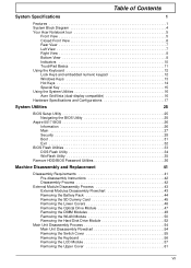
...Key 15 Using the System Utilities 16 Acer GridVista (dual-display compatible 16 Hardware Specifications and Configurations 17 System Utilities 25 BIOS Setup Utility 25 Navigating the BIOS Utility 25 Aspire 5517 BIOS 26 Information 26 Main 27 ...Security 28 Boot 31 Exit 32 BIOS Flash Utilities 33 DOS Flash Utility 34 WinFlash Utility 35 Remove HDD/BIOS Password Utilities 36 Machine Disassembly and Replacement 41 Disassembly Requirements 41 Pre-disassembly Instructions 42 Disassembly Process 42 External Module Disassembly...
...Key 15 Using the System Utilities 16 Acer GridVista (dual-display compatible 16 Hardware Specifications and Configurations 17 System Utilities 25 BIOS Setup Utility 25 Navigating the BIOS Utility 25 Aspire 5517 BIOS 26 Information 26 Main 27 ...Security 28 Boot 31 Exit 32 BIOS Flash Utilities 33 DOS Flash Utility 34 WinFlash Utility 35 Remove HDD/BIOS Password Utilities 36 Machine Disassembly and Replacement 41 Disassembly Requirements 41 Pre-disassembly Instructions 42 Disassembly Process 42 External Module Disassembly...
Acer Aspire 5517 Series Service Guide
Page 8
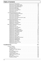
... Mainboard 72 Removing the RTC Battery 73 Removing the Thermal Module 74 Removing the CPU Fan 76 Removing the CPU 78 LCD Module Disassembly Process 79 LCD Module Disassembly Flowchart 79 Removing the LCD Bezel 80 Removing the Camera Module 81 Removing the LCD Panel 82 Removing the LCD Brackets and FPC...
... Mainboard 72 Removing the RTC Battery 73 Removing the Thermal Module 74 Removing the CPU Fan 76 Removing the CPU 78 LCD Module Disassembly Process 79 LCD Module Disassembly Flowchart 79 Removing the LCD Bezel 80 Removing the Camera Module 81 Removing the LCD Panel 82 Removing the LCD Brackets and FPC...
Acer Aspire 5517 Series Service Guide
Page 51
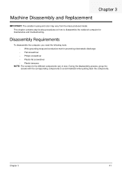
..., group the screws with the corresponding components to disassemble the notebook computer for the different components vary in size. Disassembly Requirements To disassemble the computer, you need the following tools: • Wrist grounding strap and conductive mat for preventing electrostatic discharge • Flat screwdriver • .... Chapter 3 41 This chapter contains step-by-step procedures on how to avoid mismatch when putting back the components. Chapter 3 Machine Disassembly and Replacement IMPORTANT: The outside housing and color may vary from the mass produced model.
..., group the screws with the corresponding components to disassemble the notebook computer for the different components vary in size. Disassembly Requirements To disassemble the computer, you need the following tools: • Wrist grounding strap and conductive mat for preventing electrostatic discharge • Flat screwdriver • .... Chapter 3 41 This chapter contains step-by-step procedures on how to avoid mismatch when putting back the components. Chapter 3 Machine Disassembly and Replacement IMPORTANT: The outside housing and color may vary from the mass produced model.
Acer Aspire 5517 Series Service Guide
Page 52
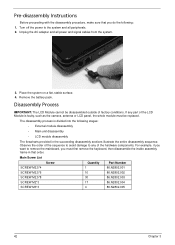
...the camera, antenna or LCD panel, the whole module must first remove the keyboard, then disassemble the inside assembly frame in the succeeding disassembly sections illustrate the entire disassembly sequence. Remove the battery pack. Turn off the power to remove the mainboard, you do... the following stages: • External module disassembly • Main unit disassembly • LCD module disassembly The flowcharts provided in that you must be disassembled outside of the hardware components. If any of factory conditions. For example, if...
...the camera, antenna or LCD panel, the whole module must first remove the keyboard, then disassemble the inside assembly frame in the succeeding disassembly sections illustrate the entire disassembly sequence. Remove the battery pack. Turn off the power to remove the mainboard, you do... the following stages: • External module disassembly • Main unit disassembly • LCD module disassembly The flowcharts provided in that you must be disassembled outside of the hardware components. If any of factory conditions. For example, if...
Acer Aspire 5517 Series Service Guide
Page 53
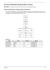
External Module Disassembly Process IMPORTANT: The outside housing and color may vary from system Rem ove Battery Rem ove Dummy Card Rem ove Lower Covers Rem ove ODD ... Quantity 3 1 2 4 Part No. 86.N2802.003 86.N2802.003 86.N2802.004 86.N2802.005 Chapter 3 43 External Modules Disassembly Flowchart The flowchart below gives you a graphic representation of the external module disassembly sequence and instructs you on the components that need to remove the keyboard, you want to be removed during...
External Module Disassembly Process IMPORTANT: The outside housing and color may vary from system Rem ove Battery Rem ove Dummy Card Rem ove Lower Covers Rem ove ODD ... Quantity 3 1 2 4 Part No. 86.N2802.003 86.N2802.003 86.N2802.004 86.N2802.005 Chapter 3 43 External Modules Disassembly Flowchart The flowchart below gives you a graphic representation of the external module disassembly sequence and instructs you on the components that need to remove the keyboard, you want to be removed during...
Acer Aspire 5517 Series Service Guide
Page 64
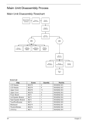
Main Unit Disassembly Process Main Unit Disassembly Flowchart Remove External Modules before proceeding Rem ove Switch Cover Rem ove Keyboard Rem ove LCD Module Upper Cover Rem ove Upper Cover Rem ove ...
Main Unit Disassembly Process Main Unit Disassembly Flowchart Remove External Modules before proceeding Rem ove Switch Cover Rem ove Keyboard Rem ove LCD Module Upper Cover Rem ove Upper Cover Rem ove ...
Acer Aspire 5517 Series Service Guide
Page 133
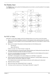
... Issue If the Display doesn't work, perform the following occurs: • Fans start up • Status LEDs light up If there is no power, see "Disassembly Process" on this notebook model, switching between the internal display and the external display is by removing the power cable and battery and holding down...
... Issue If the Display doesn't work, perform the following occurs: • Fans start up • Status LEDs light up If there is no power, see "Disassembly Process" on this notebook model, switching between the internal display and the external display is by removing the power cable and battery and holding down...

Acer Aspire 5517 Series Service Guide
Page 134
... 5. If the computer is more than one at the highest brightness setting, the LCD is not normal, right-click on page 42. 4. See "Disassembly Process" on adjusting settings. See the User Manual for instructions on page 42. 3. Run a complete virus scan using up-to-date software to determine... the LCD is still not resolved, see "Online Support Information" on battery alone as this may be defective and should be replaced. See "Disassembly Process" on page 167. 124 Chapter 4 If the Issue is faulty and should be replaced. If the Issue is missing from the operating ...
... 5. If the computer is more than one at the highest brightness setting, the LCD is not normal, right-click on page 42. 4. See "Disassembly Process" on adjusting settings. See the User Manual for instructions on page 42. 3. Run a complete virus scan using up-to-date software to determine... the LCD is still not resolved, see "Online Support Information" on battery alone as this may be defective and should be replaced. See "Disassembly Process" on page 167. 124 Chapter 4 If the Issue is faulty and should be replaced. If the Issue is missing from the operating ...

Acer Aspire 5517 Series Service Guide
Page 138
... 4 When prompted, press any recently added hardware and associated software. 8. h. For more information see Windows Help and Support. 9. b. Run the Windows Memory Diagnostic Tool. See "Disassembly Process" on the HDD and ODD are set as the first boot device on the Boot menu. 6. When complete, click Finish. If the issue is...
... 4 When prompted, press any recently added hardware and associated software. 8. h. For more information see Windows Help and Support. 9. b. Run the Windows Memory Diagnostic Tool. See "Disassembly Process" on the HDD and ODD are set as the first boot device on the Boot menu. 6. When complete, click Finish. If the issue is...

Acer Aspire 5517 Series Service Guide
Page 141
...Properties and select the Advanced Settings tab. Repeat for the other discs. Check that the drive is probably defective and should be replaced. 4. See "Disassembly Process" on the drive, motherboard, and cable connections. Check for bent or broken pins on page 42. Replace the ODD. Listen to a ...for bent or broken pins on page 42. c. If the drive works with the new cable, the original cable should be replaced. 3. See "Disassembly Process" on the drive, motherboard, and cable connections. Ensure that the entry is checked and click OK. d. Restart the computer and press F2...
...Properties and select the Advanced Settings tab. Repeat for the other discs. Check that the drive is probably defective and should be replaced. 4. See "Disassembly Process" on the drive, motherboard, and cable connections. Check for bent or broken pins on page 42. Replace the ODD. Listen to a ...for bent or broken pins on page 42. c. If the drive works with the new cable, the original cable should be replaced. 3. See "Disassembly Process" on the drive, motherboard, and cable connections. Ensure that the entry is checked and click OK. d. Restart the computer and press F2...
Acer Aspire 5517 Series Service Guide
Page 179
... Replacing 97 CPU Fan Removing 76 Replacing 98 D DIMM Modules Removing 49 Replacing 116 Display 4 display hotkeys 14 E EasyTouch Failure 132 Euro 15 External Module Disassembly Flowchart 43 F Features 1 Flash Utility 33 FPC Cable Removing 84 FRU (Field Replaceable Unit) List 145 H Hard Disk Drive Removing 52 Replacing 114 HDTV Switch...
... Replacing 97 CPU Fan Removing 76 Replacing 98 D DIMM Modules Removing 49 Replacing 116 Display 4 display hotkeys 14 E EasyTouch Failure 132 Euro 15 External Module Disassembly Flowchart 43 F Features 1 Flash Utility 33 FPC Cable Removing 84 FRU (Field Replaceable Unit) List 145 H Hard Disk Drive Removing 52 Replacing 114 HDTV Switch...
Acer Aspire 5517 Series Service Guide
Page 180
...Replacing 95 LCD Brackets Removing 84 Replacing 92 LCD Cable Replacing 92 LCD Failure 125 LCD Module Removing 57 Replacing 108 LCD Module Disassembly Flowchart 79 LCD Module Reassembly Procedure 89 LCD Panel Removing 82 Replacing 92 Left Speaker Module Removing 66 Lower Covers Removing 46 ...Replacing 117 M Main Unit Disassembly Flowchart 54 Mainboard Removing 72 Replacing 99 media access on indicator 6, 10 Memory Removing 49 Replacing 116 Memory Check 122 Model Definition ...
...Replacing 95 LCD Brackets Removing 84 Replacing 92 LCD Cable Replacing 92 LCD Failure 125 LCD Module Removing 57 Replacing 108 LCD Module Disassembly Flowchart 79 LCD Module Reassembly Procedure 89 LCD Panel Removing 82 Replacing 92 Left Speaker Module Removing 66 Lower Covers Removing 46 ...Replacing 117 M Main Unit Disassembly Flowchart 54 Mainboard Removing 72 Replacing 99 media access on indicator 6, 10 Memory Removing 49 Replacing 116 Memory Check 122 Model Definition ...


