
Aspire 5335 / 5735 / 5735Z Service Guide
Page 7
...Acer GridVista (dual-display compatible 24 Hardware Specifications and Configurations 26 System Utilities 33 BIOS Setup Utility 33 Navigating the BIOS Utility 34 Information 35 Main 36 Security 38 Boot 42 Exit 43 BIOS Flash Utility 44 Remove HDD/BIOS Utility 45 Machine Disassembly and Replacement 47 Disassembly... Requirements 47 General Information 48 Pre-disassembly Instructions 48 Disassembly Process 48 External Module Disassembly Process 49 External Modules Disassembly Flowchart 49 Removing the ...
...Acer GridVista (dual-display compatible 24 Hardware Specifications and Configurations 26 System Utilities 33 BIOS Setup Utility 33 Navigating the BIOS Utility 34 Information 35 Main 36 Security 38 Boot 42 Exit 43 BIOS Flash Utility 44 Remove HDD/BIOS Utility 45 Machine Disassembly and Replacement 47 Disassembly... Requirements 47 General Information 48 Pre-disassembly Instructions 48 Disassembly Process 48 External Module Disassembly Process 49 External Modules Disassembly Flowchart 49 Removing the ...
Aspire 5335 / 5735 / 5735Z Service Guide
Page 8
... 80 Removing the Main Board 82 Removing the USB Board Module 84 Removing the Bluetooth Modules 86 LCD Module Disassembly Process 87 LCD Module Disassembly Flowchart 87 Removing the LCD Bezel 88 Removing the LCD panel with the Brackets 89 Removing the Inverter Board ... Password Check 119 BIOS Recovery by Crisis Disk 120 FRU (Field Replaceable Unit) List 121 Aspire 5735/5735Z/5335 Series Exploded Diagram 122 Model Definition and Configuration 130 Aspire 5735/5735Z/5335 Series 130 Test Compatible Components 155 Microsoft® Windows® Vista Environment Test 156 VIII
... 80 Removing the Main Board 82 Removing the USB Board Module 84 Removing the Bluetooth Modules 86 LCD Module Disassembly Process 87 LCD Module Disassembly Flowchart 87 Removing the LCD Bezel 88 Removing the LCD panel with the Brackets 89 Removing the Inverter Board ... Password Check 119 BIOS Recovery by Crisis Disk 120 FRU (Field Replaceable Unit) List 121 Aspire 5735/5735Z/5335 Series Exploded Diagram 122 Model Definition and Configuration 130 Aspire 5735/5735Z/5335 Series 130 Test Compatible Components 155 Microsoft® Windows® Vista Environment Test 156 VIII
Aspire 5335 / 5735 / 5735Z Service Guide
Page 57
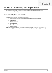
..., group the screws with the corresponding components to disassemble the notebook computer for the different components vary in size. Disassembly Requirements To disassemble the computer, you need the following tools: • Wrist grounding strap and conductive mat for preventing electrostatic discharge &#...8226; Hex screwdriver • Plastic flat screwdriver • Plastic tweezers NOTE: The screws for maintenance and troubleshooting. Chapter 3 Machine Disassembly and Replacement This chapter contains step-by-step procedures on how to avoid mismatch when putting back the components.
..., group the screws with the corresponding components to disassemble the notebook computer for the different components vary in size. Disassembly Requirements To disassemble the computer, you need the following tools: • Wrist grounding strap and conductive mat for preventing electrostatic discharge &#...8226; Hex screwdriver • Plastic flat screwdriver • Plastic tweezers NOTE: The screws for maintenance and troubleshooting. Chapter 3 Machine Disassembly and Replacement This chapter contains step-by-step procedures on how to avoid mismatch when putting back the components.
Aspire 5335 / 5735 / 5735Z Service Guide
Page 58
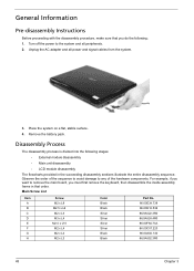
... the main board, you must first remove the keyboard, then disassemble the inside assembly frame in the succeeding disassembly sections illustrate the entire disassembly sequence. Disassembly Process The disassembly process is divided into the following stages: • External module disassembly • Main unit disassembly • LCD module disassembly The flowcharts provided in that you do the following: 1. General...
... the main board, you must first remove the keyboard, then disassemble the inside assembly frame in the succeeding disassembly sections illustrate the entire disassembly sequence. Disassembly Process The disassembly process is divided into the following stages: • External module disassembly • Main unit disassembly • LCD module disassembly The flowcharts provided in that you do the following: 1. General...

Aspire 5335 / 5735 / 5735Z Service Guide
Page 59
... inside assembly frame in that need to be removed during servicing. External Module Disassembly Process External Modules Disassembly Flowchart The flowchart below gives you a graphic representation on the components that order. EXTERNAL MODULE DISASSEMBLY TURN OFF POWER AND PERIPHERALS UNPLUG POWER CABLES REMOVE BATTERY PACK SD DUMMY CARD ExpressCard DUMMY CARD Captive Screwx4...
... inside assembly frame in that need to be removed during servicing. External Module Disassembly Process External Modules Disassembly Flowchart The flowchart below gives you a graphic representation on the components that order. EXTERNAL MODULE DISASSEMBLY TURN OFF POWER AND PERIPHERALS UNPLUG POWER CABLES REMOVE BATTERY PACK SD DUMMY CARD ExpressCard DUMMY CARD Captive Screwx4...
Aspire 5335 / 5735 / 5735Z Service Guide
Page 71
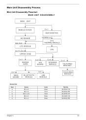
Main Unit Disassembly Process Main Unit Disassembly Flowchart MAIN UNIT DISASSEMBLY MAIN UNIT MIDDLE COVER KEYBOARD Ax2, Ex2 LCD MODULE A x 11, G x 4 UPPER CASE C x 1 HEAT SINK FAN SCREW X 4 CPU THERMAL MODULE CPU C x 1 MODEM CARD C x 1 LED BOARD C x 4 SPEAKER MODULE C x 2 TOUCHPAD BRACKET Cx1 MAIN BOARD BLUETOOTH MODULE Cx1 USB MODULE TOUCHPAD MODULE Screw List Item A C E G H Screw M2 x L8 M2 x L3 M2.5 x L10 M2 x L4 M2 x L3 Color Black Silver Silver Black Black Part No. 86.00E34.738 86.9A522.3R0 86.00F84.73A 86.00A02.140 86.9A552.3R0 Chapter 3 61
Main Unit Disassembly Process Main Unit Disassembly Flowchart MAIN UNIT DISASSEMBLY MAIN UNIT MIDDLE COVER KEYBOARD Ax2, Ex2 LCD MODULE A x 11, G x 4 UPPER CASE C x 1 HEAT SINK FAN SCREW X 4 CPU THERMAL MODULE CPU C x 1 MODEM CARD C x 1 LED BOARD C x 4 SPEAKER MODULE C x 2 TOUCHPAD BRACKET Cx1 MAIN BOARD BLUETOOTH MODULE Cx1 USB MODULE TOUCHPAD MODULE Screw List Item A C E G H Screw M2 x L8 M2 x L3 M2.5 x L10 M2 x L4 M2 x L3 Color Black Silver Silver Black Black Part No. 86.00E34.738 86.9A522.3R0 86.00F84.73A 86.00A02.140 86.9A552.3R0 Chapter 3 61
Aspire 5335 / 5735 / 5735Z Service Guide
Page 153
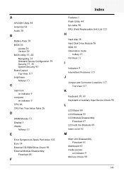
...26 D DIMM Module 53 Display 3 display hotkeys 13 E Error Symptom-to-Spare Part Index 102 Euro 14 External CD-ROM Drive Check 98 External Module Disassembly Flowchart 49 F Index Features 1 Flash Utility 44 fpc cable 90 FRU (Field Replaceable Unit) List 121 H Hard disk 28 Hard Disk Drive Module 56...Connector Locations 117 Top View 117 K Keyboard 30, 63 Keyboard or Auxiliary Input Device Check 98 L LCD Bezel 88 LCD Brackets 93 LCD Module Disassembly Flowchart 87 LCD with the Brackets 89 lower cover 52 M Main Unit Disassembly Flowchart 61 Mainboard 82 media access on indicator 9 Memory Check 99 143
...26 D DIMM Module 53 Display 3 display hotkeys 13 E Error Symptom-to-Spare Part Index 102 Euro 14 External CD-ROM Drive Check 98 External Module Disassembly Flowchart 49 F Index Features 1 Flash Utility 44 fpc cable 90 FRU (Field Replaceable Unit) List 121 H Hard disk 28 Hard Disk Drive Module 56...Connector Locations 117 Top View 117 K Keyboard 30, 63 Keyboard or Auxiliary Input Device Check 98 L LCD Bezel 88 LCD Brackets 93 LCD Module Disassembly Flowchart 87 LCD with the Brackets 89 lower cover 52 M Main Unit Disassembly Flowchart 61 Mainboard 82 media access on indicator 9 Memory Check 99 143


