Aspire 5230 Service Guide
Page 7
...and embedded numeric keypad 12 Windows Keys 13 Hot Keys 14 Special Key 15 Using the System Utilities 16 Acer GridVista (dual-display compatible 16 Launch Manager 17 Hardware Specifications and Configurations 18 System Utilities 25 BIOS Setup Utility... HDD/BIOS Password Utilities 41 Miscellaneous Utilities 44 Machine Disassembly and Replacement 45 Disassembly Requirements 45 General Information 46 Pre-disassembly Instructions 46 Disassembly Process 46 External Module Disassembly Process 47 External Modules Disassembly Flowchart 47 Removing the Battery Pack 48 Removing the ...
...and embedded numeric keypad 12 Windows Keys 13 Hot Keys 14 Special Key 15 Using the System Utilities 16 Acer GridVista (dual-display compatible 16 Launch Manager 17 Hardware Specifications and Configurations 18 System Utilities 25 BIOS Setup Utility... HDD/BIOS Password Utilities 41 Miscellaneous Utilities 44 Machine Disassembly and Replacement 45 Disassembly Requirements 45 General Information 46 Pre-disassembly Instructions 46 Disassembly Process 46 External Module Disassembly Process 47 External Modules Disassembly Flowchart 47 Removing the Battery Pack 48 Removing the ...
Aspire 5230 Service Guide
Page 8
Table of Contents Removing the Hard Disk Drive Module 58 Removing the Optical Drive Module 60 Main Unit Disassembly Process 62 Main Unit Disassembly Flowchart 62 Removing the Switch Cover 63 Removing the Keyboard 64 Removing the Antenna 65 Removing the LCD Module 67 Removing the Upper ... Removing the RJ-11 Port 93 Removing the Thermal Module 94 Removing the CPU 96 Removing the VGA Module 97 LCD Module Disassembly Process 98 LCD Module Disassembly Flowchart 98 Removing the LCD Bezel 99 Removing the Inverter Board 100 Removing the Camera Module 102 Removing the LCD Panel 104 ...
Table of Contents Removing the Hard Disk Drive Module 58 Removing the Optical Drive Module 60 Main Unit Disassembly Process 62 Main Unit Disassembly Flowchart 62 Removing the Switch Cover 63 Removing the Keyboard 64 Removing the Antenna 65 Removing the LCD Module 67 Removing the Upper ... Removing the RJ-11 Port 93 Removing the Thermal Module 94 Removing the CPU 96 Removing the VGA Module 97 LCD Module Disassembly Process 98 LCD Module Disassembly Flowchart 98 Removing the LCD Bezel 99 Removing the Inverter Board 100 Removing the Camera Module 102 Removing the LCD Panel 104 ...

Aspire 5230 Service Guide
Page 57
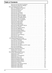
... flat screwdriver • Plastic tweezers NOTE: The screws for maintenance and troubleshooting. During the disassembly process, group the screws with the corresponding components to disassemble the notebook computer for the different components vary in size. Chapter 3 45 Machine Disassembly and Replacement Chapter 3 This chapter contains step-by-step procedures on how to avoid...
... flat screwdriver • Plastic tweezers NOTE: The screws for maintenance and troubleshooting. During the disassembly process, group the screws with the corresponding components to disassemble the notebook computer for the different components vary in size. Chapter 3 45 Machine Disassembly and Replacement Chapter 3 This chapter contains step-by-step procedures on how to avoid...
Aspire 5230 Service Guide
Page 58
....5*8 (NL) 15 M2.5*5 (NL) 22 M2.5*3 (NL) 2 M2*3 (NL) 36 M2.5*4 (NL) 2 M2*6 (NL) 4 M2*4-NI (NL) 5 M3*3 (NL) 4 M2*6.5 4 M2.5*5.0 2 M2.5*6.5 4 46 Chapter 3 Disassembly Process The disassembly process is divided into the following : 1. Place the system on a flat, stable surface. 4. Observe the order of the sequence to avoid damage to the...
....5*8 (NL) 15 M2.5*5 (NL) 22 M2.5*3 (NL) 2 M2*3 (NL) 36 M2.5*4 (NL) 2 M2*6 (NL) 4 M2*4-NI (NL) 5 M3*3 (NL) 4 M2*6.5 4 M2.5*5.0 2 M2.5*6.5 4 46 Chapter 3 Disassembly Process The disassembly process is divided into the following : 1. Place the system on a flat, stable surface. 4. Observe the order of the sequence to avoid damage to the...
Aspire 5230 Service Guide
Page 59
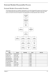
... The flowchart below gives you a graphic representation on the entire disassembly sequence and instructs you must first remove the keyboard, then disassemble the inside assembly frame in that need to be removed during servicing. Screw List Step Memory Cover HDD Cover WLAN Cover WLAN Module WLAN Bracket ...
... The flowchart below gives you a graphic representation on the entire disassembly sequence and instructs you must first remove the keyboard, then disassemble the inside assembly frame in that need to be removed during servicing. Screw List Step Memory Cover HDD Cover WLAN Cover WLAN Module WLAN Bracket ...
Aspire 5230 Service Guide
Page 155
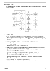
.... Reference Product pages for 10 seconds. Drain any memory cards and CD/DVD discs. If the POST or video appears on the external display, see "Disassembly Process" on page 145. 5. Make sure that the internal display is still not resolved, see "Online Support Information" on page 142. 3. Restart the computer. No...
.... Reference Product pages for 10 seconds. Drain any memory cards and CD/DVD discs. If the POST or video appears on the external display, see "Disassembly Process" on page 145. 5. Make sure that the internal display is still not resolved, see "Online Support Information" on page 142. 3. Restart the computer. No...
Aspire 5230 Service Guide
Page 156
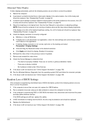
..." on page 46. 5. See "Disassembly Process" on page 46. 3. Check the display resolution is more than one year old, replace the CMOS battery. 2. Click and drag the Resolution slider to ... not resolved, see "Online Support Information" on battery alone as this may be defective and should be replaced. Click Apply and check the display. See "Disassembly Process" on adjusting settings. Readjust if necessary. 6. b. If display size is not normal, right-click on page 189. 10. There are no red Xs or...
..." on page 46. 5. See "Disassembly Process" on page 46. 3. Check the display resolution is more than one year old, replace the CMOS battery. 2. Click and drag the Resolution slider to ... not resolved, see "Online Support Information" on battery alone as this may be defective and should be replaced. Click Apply and check the display. See "Disassembly Process" on adjusting settings. Readjust if necessary. 6. b. If display size is not normal, right-click on page 189. 10. There are no red Xs or...
Aspire 5230 Service Guide
Page 161
... the problem. 4. Restore system and file settings from a command prompt. If the issue is discovered, follow the onscreen information to the operating system DVD. See "Disassembly Process" on the Boot menu. 6. Run a complete virus scan using System Restore. Click Next. Select the appropriate operating system, and click Next. NOTE: Click Load...
... the problem. 4. Restore system and file settings from a command prompt. If the issue is discovered, follow the onscreen information to the operating system DVD. See "Disassembly Process" on the Boot menu. 6. Run a complete virus scan using System Restore. Click Next. Select the appropriate operating system, and click Next. NOTE: Click Load...
Aspire 5230 Service Guide
Page 164
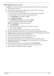
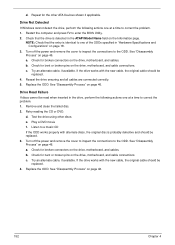
... the ODD. Turn off the power and remove the cover to inspect the connections to the ODD. See "Disassembly Process" on page 46. Remove and clean the failed disc. 2. See "Disassembly Process" on page 46. a. Check for broken connectors on page 46. 152 Chapter 4 Try an alternate... cable, if available. See "Disassembly Process" on the drive, motherboard, and cables. See "Disassembly Process" on the drive, motherboard, and cables. Check for bent or broken pins on the drive, motherboard, and cable...
... the ODD. Turn off the power and remove the cover to inspect the connections to the ODD. See "Disassembly Process" on page 46. Remove and clean the failed disc. 2. See "Disassembly Process" on page 46. a. Check for broken connectors on page 46. 152 Chapter 4 Try an alternate... cable, if available. See "Disassembly Process" on the drive, motherboard, and cables. See "Disassembly Process" on the drive, motherboard, and cables. Check for bent or broken pins on the drive, motherboard, and cable...
Aspire 5230 Service Guide
Page 204
Keyboard Failure 145 L Launch Board 81 LCD Bezel 99 LCD Brackets 105 LCD Failure 145 LCD Module Disassembly Flowchart 98 LCD Panel 104 lower cover 51 M Main Unit Disassembly Flowchart 62 Mainboard 91 media access on indicator 10 MediaTouch Button Failure 155 Memory Check 142 Model Definition 182 Modem Failure 153 Modem Module...
Keyboard Failure 145 L Launch Board 81 LCD Bezel 99 LCD Brackets 105 LCD Failure 145 LCD Module Disassembly Flowchart 98 LCD Panel 104 lower cover 51 M Main Unit Disassembly Flowchart 62 Mainboard 91 media access on indicator 10 MediaTouch Button Failure 155 Memory Check 142 Model Definition 182 Modem Failure 153 Modem Module...


