Aspire 5230 Service Guide
Page 8
...Disassembly Process 62 Main Unit Disassembly Flowchart 62 Removing the Switch Cover 63 Removing the Keyboard 64 Removing the Antenna 65 Removing the LCD Module 67 Removing the Upper Cover 69 Removing the Finger Print Reader 74 Removing the Upper Right Saddle 75 Removing the Left ... 100 Removing the Camera Module 102 Removing the LCD Panel 104 Removing the LCD Brackets and FPC Cable 105 Removing the Antennas 106 Removing the MIC Module 107 LCD Module Reassembly Procedure 108 Replacing the LCD Panel 108 Replacing the LCD Bezel 112 Main Module Reassembly Procedure 113 Replacing ...
...Disassembly Process 62 Main Unit Disassembly Flowchart 62 Removing the Switch Cover 63 Removing the Keyboard 64 Removing the Antenna 65 Removing the LCD Module 67 Removing the Upper Cover 69 Removing the Finger Print Reader 74 Removing the Upper Right Saddle 75 Removing the Left ... 100 Removing the Camera Module 102 Removing the LCD Panel 104 Removing the LCD Brackets and FPC Cable 105 Removing the Antennas 106 Removing the MIC Module 107 LCD Module Reassembly Procedure 108 Replacing the LCD Panel 108 Replacing the LCD Bezel 112 Main Module Reassembly Procedure 113 Replacing ...
Aspire 5230 Service Guide
Page 9
...Finger Print Reader 126 Replacing the Touch Pad Bracket 126 Replacing the Left Speaker Module 127 Replacing the LCD Module 129 Replacing the Antenna Cables 131 Replacing the Keyboard 132 Replacing the Switch Cover 132 Replacing ...141 Common Problems 141 Power On Issue 142 No Display Issue 143 Random Loss of BIOS Settings 144 LCD Failure 145 Built-In Keyboard Failure 145 Touchpad Failure 146 Internal Speaker Failure 146 Internal Microphone Failure 148... by Crisis Disk 166 FRU (Field Replaceable Unit) List 169 Aspire 5530 Exploded Diagram 170 Aspire 5530 FRU List 171 IX
...Finger Print Reader 126 Replacing the Touch Pad Bracket 126 Replacing the Left Speaker Module 127 Replacing the LCD Module 129 Replacing the Antenna Cables 131 Replacing the Keyboard 132 Replacing the Switch Cover 132 Replacing ...141 Common Problems 141 Power On Issue 142 No Display Issue 143 Random Loss of BIOS Settings 144 LCD Failure 145 Built-In Keyboard Failure 145 Touchpad Failure 146 Internal Speaker Failure 146 Internal Microphone Failure 148... by Crisis Disk 166 FRU (Field Replaceable Unit) List 169 Aspire 5530 Exploded Diagram 170 Aspire 5530 FRU List 171 IX
Aspire 5230 Service Guide
Page 15
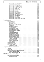
... Eye Display screen Power button Description Internal microphone for launching frequently used program. Your Acer Notebook tour After knowing your computer features, let us show you use the computer. Turns the computer on and off. Comfortable support area for ...and right speakers deliver stereo audio output. Touch-sensitive pointing device which functions like a computer mouse. 5 Buttons for sound recording. Also called Liquid-Crystal Display (LCD), displays computer output. Web camera for your hands when you around your computer. For entering data into your new computer.
... Eye Display screen Power button Description Internal microphone for launching frequently used program. Your Acer Notebook tour After knowing your computer features, let us show you use the computer. Turns the computer on and off. Comfortable support area for ...and right speakers deliver stereo audio output. Touch-sensitive pointing device which functions like a computer mouse. 5 Buttons for sound recording. Also called Liquid-Crystal Display (LCD), displays computer output. Web camera for your hands when you around your computer. For entering data into your new computer.
Aspire 5230 Service Guide
Page 17
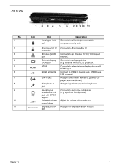
... from external microphones. Chapter 1 7 audio CD player, stereo walkman). Adjust the volume of the audio-out. external monitor, LCD projector). Accepts one ExpressCard/54 module. Accepts audio line-in jack Headphones/ speaker/line-out jack with HDMI input. Connects to ...an Ethernet 10/100/1000-based network. Connects to a television or display device with S/PDIF support Unlimited volume control wheel ExpressCard/54 slot Connects to Acer EasyPort IV. USB mouse, USB camera). speakers, headphones). Connects to a display device (e.g. Left View No. 1 2 3 4 5 6 7 8...
... from external microphones. Chapter 1 7 audio CD player, stereo walkman). Adjust the volume of the audio-out. external monitor, LCD projector). Accepts one ExpressCard/54 module. Accepts audio line-in jack Headphones/ speaker/line-out jack with HDMI input. Connects to ...an Ethernet 10/100/1000-based network. Connects to a television or display device with S/PDIF support Unlimited volume control wheel ExpressCard/54 slot Connects to Acer EasyPort IV. USB mouse, USB camera). speakers, headphones). Connects to a display device (e.g. Left View No. 1 2 3 4 5 6 7 8...

Aspire 5230 Service Guide
Page 35
x 6.1 max. 1 channel LVDS 262K colors (RGB 6-bit) 40/40 15/30 0 to +50 -20 to +60 LCD Camera Item Vendor Model Name Type Dimension (L x W x H mm) Sensor Optical Size Pixel Resolution Pixel Size Specification Bison Electronics Suyin BN30V4O7-010 ...size CMOS sensor OV7725 CMOS Sensor 350K Pixel 1/4 inch F/2.0 640(H) X 480(V) VGA 640X480 6.0µm X 6.0µm 6.0µm X6.0µm Chapter 1 25 x 222.0 typ. LCD 15.4" Item Vendor/model name Screen Diagonal (mm) Active Area (mm) Display resolution (pixels) Pixel Pitch Pixel Arrangement Display Mode Typical White Luminance (cd/m2...
x 6.1 max. 1 channel LVDS 262K colors (RGB 6-bit) 40/40 15/30 0 to +50 -20 to +60 LCD Camera Item Vendor Model Name Type Dimension (L x W x H mm) Sensor Optical Size Pixel Resolution Pixel Size Specification Bison Electronics Suyin BN30V4O7-010 ...size CMOS sensor OV7725 CMOS Sensor 350K Pixel 1/4 inch F/2.0 640(H) X 480(V) VGA 640X480 6.0µm X 6.0µm 6.0µm X6.0µm Chapter 1 25 x 222.0 typ. LCD 15.4" Item Vendor/model name Screen Diagonal (mm) Active Area (mm) Display resolution (pixels) Pixel Pitch Pixel Arrangement Display Mode Typical White Luminance (cd/m2...

Aspire 5230 Service Guide
Page 36
LCD Inverter Item Vendor & model name Brightness conditions Input voltage (V) Input current (mA) Output voltage (V, rms) Output current (mA, rms) Output voltage frequency (k Hz) AC Adapter ...; Suspend to RAM or Suspend to Disk mode, by time out or by hot key • HDD Local Stand-By mode by time out • LCD Local Stand-By mode by time out • Low battery alarm by beep • Auto-backlight off when...
LCD Inverter Item Vendor & model name Brightness conditions Input voltage (V) Input current (mA) Output voltage (V, rms) Output current (mA, rms) Output voltage frequency (k Hz) AC Adapter ...; Suspend to RAM or Suspend to Disk mode, by time out or by hot key • HDD Local Stand-By mode by time out • LCD Local Stand-By mode by time out • Low battery alarm by beep • Auto-backlight off when...
Aspire 5230 Service Guide
Page 58
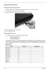
... peripherals. 2. For example, if you want to remove the main board, you do the following stages: • External module disassembly • Main unit disassembly • LCD module disassembly The flowcharts provided in that order. Turn off the power to any of the sequence to avoid damage to the system and all...
... peripherals. 2. For example, if you want to remove the main board, you do the following stages: • External module disassembly • Main unit disassembly • LCD module disassembly The flowcharts provided in that order. Turn off the power to any of the sequence to avoid damage to the system and all...
Aspire 5230 Service Guide
Page 76
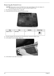
It is recommended that only fingers are used to the outer casing. Locate and remove the three securing screws as shown, leftside first. 5. Step Switch Cover Size M2*3(NL) Quantity 3 Screw Type 3. Lift the Switch Cover as shown. Removing the Switch Cover CAUTION: Using tools to remove the Switch Cover may cause damage to remove the Switch Cover. 1. See "Removing the Battery Pack" on page 48. 2. Lift the Switch Cover clear of the chassis. 64 Chapter 3 Turn the computer over and open the LCD module fully to expose the Switch Cover. 4.
It is recommended that only fingers are used to the outer casing. Locate and remove the three securing screws as shown, leftside first. 5. Step Switch Cover Size M2*3(NL) Quantity 3 Screw Type 3. Lift the Switch Cover as shown. Removing the Switch Cover CAUTION: Using tools to remove the Switch Cover may cause damage to remove the Switch Cover. 1. See "Removing the Battery Pack" on page 48. 2. Lift the Switch Cover clear of the chassis. 64 Chapter 3 Turn the computer over and open the LCD module fully to expose the Switch Cover. 4.
Aspire 5230 Service Guide
Page 80
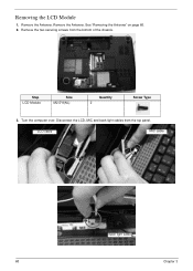
Remove the Antenna. LCD cable MIC cable Back light cable 68 Chapter 3 Removing the LCD Module 1. Remove the Antenna. See "Removing the Antenna" on page 66. 2. Turn the computer over. Disconnect the LCD, MIC and back light cables from the bottom of the chassis. Remove the two securing screws from the top panel. Step LCD Module Size M2.5*8(NL) Quantity 2 Screw Type 3.
Remove the Antenna. LCD cable MIC cable Back light cable 68 Chapter 3 Removing the LCD Module 1. Remove the Antenna. See "Removing the Antenna" on page 66. 2. Turn the computer over. Disconnect the LCD, MIC and back light cables from the bottom of the chassis. Remove the two securing screws from the top panel. Step LCD Module Size M2.5*8(NL) Quantity 2 Screw Type 3.

Aspire 5230 Service Guide
Page 81
Screw Type Chapter 3 69 4. Step LCD Hinges (Red call out) LCD Hinges (Blue call out) Size M2.5*6 (NL) M2.5*10 (NL) Quantity 2 2 5. Remove the four securing screws (two on each side) connecting the LCD module. Carefully remove the LCD module from the chassis.
Screw Type Chapter 3 69 4. Step LCD Hinges (Red call out) LCD Hinges (Blue call out) Size M2.5*6 (NL) M2.5*10 (NL) Quantity 2 2 5. Remove the four securing screws (two on each side) connecting the LCD module. Carefully remove the LCD module from the chassis.

Aspire 5230 Service Guide
Page 82
Step Upper Cover Size M2.5*10 (NL) Quantity 9 3. Turn the computer over . Removing the Upper Cover 1. Remove the LCD Module. See "Removing the LCD Module" on the bottom panel. Remove the nine screws on page 68. 2. Screw Type Step Upper Cover Size M2.5*4 (NL) Quantity 5 Screw Type 70 Chapter 3 Turn the computer over . Remove the five screws on the top panel.
Step Upper Cover Size M2.5*10 (NL) Quantity 9 3. Turn the computer over . Removing the Upper Cover 1. Remove the LCD Module. See "Removing the LCD Module" on the bottom panel. Remove the nine screws on page 68. 2. Screw Type Step Upper Cover Size M2.5*4 (NL) Quantity 5 Screw Type 70 Chapter 3 Turn the computer over . Remove the five screws on the top panel.
Aspire 5230 Service Guide
Page 102
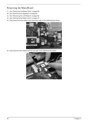
See "Removing the Upper Cover" on page 48. 2. Disconnect the three cables from the top right of the mainboard as shown. 90 Chapter 3 See "Removing the Battery Pack" on page 70. 5. Disconnect the two cables from the bottom right of the mainboard as shown. 6. See "Removing the Keyboard" on page 68. 4. See "Removing the LCD Module" on page 65. 3. Removing the Main Board 1.
See "Removing the Upper Cover" on page 48. 2. Disconnect the three cables from the top right of the mainboard as shown. 90 Chapter 3 See "Removing the Battery Pack" on page 70. 5. Disconnect the two cables from the bottom right of the mainboard as shown. 6. See "Removing the Keyboard" on page 68. 4. See "Removing the LCD Module" on page 65. 3. Removing the Main Board 1.
Aspire 5230 Service Guide
Page 105
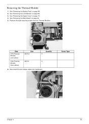
See "Removing the Battery Pack" on page 90. 5. See "Removing the Main Board" on page 48. 2. Remove the eight securing screws from mainboard. Step CPU Thermal Module (red callout) VGA Thermal Module (blue callout) Size M2*6.5 M2*L3 Quantity 4 4 6. Removing the Thermal Module 1. See "Removing the Upper Cover" on page 68. 3. Disconnect the fan module cable from the Thermal Modules. See "Removing the LCD Module" on page 70. 4. Screw Type Chapter 3 93
See "Removing the Battery Pack" on page 90. 5. See "Removing the Main Board" on page 48. 2. Remove the eight securing screws from mainboard. Step CPU Thermal Module (red callout) VGA Thermal Module (blue callout) Size M2*6.5 M2*L3 Quantity 4 4 6. Removing the Thermal Module 1. See "Removing the Upper Cover" on page 68. 3. Disconnect the fan module cable from the Thermal Modules. See "Removing the LCD Module" on page 70. 4. Screw Type Chapter 3 93

Aspire 5230 Service Guide
Page 110
See "Removing the Battery Pack" on page 68. 3. Remove the four securing screws from the LCD Module. Removing the LCD Bezel 1. Remove the two upper and two lower bezel screw caps. See "Removing the LCD Module" on page 48. 2. Step LCD Bezel Size M2.5*5 (NL) Quantity 4 4. Screw Type 98 Chapter 3 Lift up the bezel, topside first, and remove it from the LCD module.
See "Removing the Battery Pack" on page 68. 3. Remove the four securing screws from the LCD Module. Removing the LCD Bezel 1. Remove the two upper and two lower bezel screw caps. See "Removing the LCD Module" on page 48. 2. Step LCD Bezel Size M2.5*5 (NL) Quantity 4 4. Screw Type 98 Chapter 3 Lift up the bezel, topside first, and remove it from the LCD module.
Aspire 5230 Service Guide
Page 111
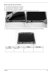
See "Removing the Battery Pack" on page 68. 3. Remove the securing tapes from the Inverter board and lift the board clear of the Inverter board as shown. 5. Remove the two securing screws from the left and right sides of the LCD Module. See "Removing the LCD Module" on page 48. 2. Step Inverter Board Size M2.5*6 (NL) Quantity 2 Screw Type Chapter 3 99 See "Removing the LCD Bezel" on page 98. 4. Removing the Inverter Board 1.
See "Removing the Battery Pack" on page 68. 3. Remove the securing tapes from the Inverter board and lift the board clear of the Inverter board as shown. 5. Remove the two securing screws from the left and right sides of the LCD Module. See "Removing the LCD Module" on page 48. 2. Step Inverter Board Size M2.5*6 (NL) Quantity 2 Screw Type Chapter 3 99 See "Removing the LCD Bezel" on page 98. 4. Removing the Inverter Board 1.
Aspire 5230 Service Guide
Page 113
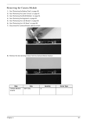
See "Removing the LCD Bezel" on page 51. 3. See "Removing the Lower Covers" on page 98. 7. See "Removing the LCD Module" on page 65. 5. Remove the two securing screws from the Camera Module bracket. See "Removing the Keyboard" on page 68. 6. Step Camera Module bracket Size M2*3 (NL) Quantity 2 Screw Type Chapter 3 101 See "Removing the WLAN Module" on page 48. 2. Removing the Camera Module 1. Disconnect the Camera Module cable as shown. 8. See "Removing the Battery Pack" on page 54. 4.
See "Removing the LCD Bezel" on page 51. 3. See "Removing the Lower Covers" on page 98. 7. See "Removing the LCD Module" on page 65. 5. Remove the two securing screws from the Camera Module bracket. See "Removing the Keyboard" on page 68. 6. Step Camera Module bracket Size M2*3 (NL) Quantity 2 Screw Type Chapter 3 101 See "Removing the WLAN Module" on page 48. 2. Removing the Camera Module 1. Disconnect the Camera Module cable as shown. 8. See "Removing the Battery Pack" on page 54. 4.

Aspire 5230 Service Guide
Page 114
9. Lift the Camera Module clear of the LCD Module. 10. Screw Type 102 Chapter 3 Remove the securing screw from the bracket. Remove the camera board from the camera board. Step Camera Board Size M2*3 (NL) Quantity 1 11.
9. Lift the Camera Module clear of the LCD Module. 10. Screw Type 102 Chapter 3 Remove the securing screw from the bracket. Remove the camera board from the camera board. Step Camera Board Size M2*3 (NL) Quantity 1 11.
Aspire 5230 Service Guide
Page 115
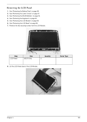
Removing the LCD Panel 1. Lift the LCD Panel clear of the LCD Module. See "Removing the Keyboard" on page 48. 2. Step LCD Panel Size M2.5*6 (NL) Quantity 2 8. See "Removing the Battery Pack" on page 65. 5. See "Removing the WLAN Module" on page 51. 3. Screw Type Chapter 3 103 See "Removing the Lower Covers" on page 54. 4. See "Removing the LCD Module" on page 98. 7. See "Removing the LCD Bezel" on page 68. 6. Remove the two securing screws from the LCD Module.
Removing the LCD Panel 1. Lift the LCD Panel clear of the LCD Module. See "Removing the Keyboard" on page 48. 2. Step LCD Panel Size M2.5*6 (NL) Quantity 2 8. See "Removing the Battery Pack" on page 65. 5. See "Removing the WLAN Module" on page 51. 3. Screw Type Chapter 3 103 See "Removing the Lower Covers" on page 54. 4. See "Removing the LCD Module" on page 98. 7. See "Removing the LCD Bezel" on page 68. 6. Remove the two securing screws from the LCD Module.
Aspire 5230 Service Guide
Page 116
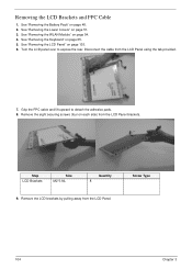
... Size M2*3 NL Quantity 8 9. Grip the FPC cable and lift upward to expose the rear. Remove the LCD brackets by pulling away from the LCD Panel using the tab provided. 7. Disconnect the cable from the LCD Panel. See "Removing the Battery Pack" on page 65. 5. See "Removing the Lower Covers" on page 54...
... Size M2*3 NL Quantity 8 9. Grip the FPC cable and lift upward to expose the rear. Remove the LCD brackets by pulling away from the LCD Panel using the tab provided. 7. Disconnect the cable from the LCD Panel. See "Removing the Battery Pack" on page 65. 5. See "Removing the Lower Covers" on page 54...
Aspire 5230 Service Guide
Page 117
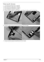
See "Removing the WLAN Module" on page 103. 5. See "Removing the LCD Panel" on page 54. 4. Remove the strips holding the antenna cables in place. Remove the antenna cables and assembly from obstructions. 6. Removing the Antennas 1. See "Removing the Lower Covers" on page 48. 2. Ensure the cables are free from the LCD module. Chapter 3 105 Remove the tabs securing the left and right antennas to the LCD module. 7. See "Removing the Battery Pack" on page 51. 3.
See "Removing the WLAN Module" on page 103. 5. See "Removing the LCD Panel" on page 54. 4. Remove the strips holding the antenna cables in place. Remove the antenna cables and assembly from obstructions. 6. Removing the Antennas 1. See "Removing the Lower Covers" on page 48. 2. Ensure the cables are free from the LCD module. Chapter 3 105 Remove the tabs securing the left and right antennas to the LCD module. 7. See "Removing the Battery Pack" on page 51. 3.


