
Aspire 5050 / 3050 User's Guide - EN
Page 5
... before servicing. • To avoid the remote risk of electric shock from children. Use of another battery may explode if not handled properly. Do not disassemble or dispose of used batteries.
... before servicing. • To avoid the remote risk of electric shock from children. Use of another battery may explode if not handled properly. Do not disassemble or dispose of used batteries.

Aspire 5050 / 3050 User's Guide - EN
Page 99
...;LING NAR DEKSEL ÅPNESSTIRR IKKE INN I STRÅLEN LCD pixel statement The LCD unit is prohibited. AVOID EXPOSURE TO BEAM. Reverse engineering or disassembly is produced with this copyright protection technology must be authorized by Macrovision, and is located on the recorded image and does not constitute a malfunction. English...
...;LING NAR DEKSEL ÅPNESSTIRR IKKE INN I STRÅLEN LCD pixel statement The LCD unit is prohibited. AVOID EXPOSURE TO BEAM. Reverse engineering or disassembly is produced with this copyright protection technology must be authorized by Macrovision, and is located on the recorded image and does not constitute a malfunction. English...

Aspire 5050 / 3050 Service Guide
Page 7
...Acer GridVista (dual-display compatible 31 Launch Manager 32 Hardware Specifications and Configurations 33 Chapter 2 System Utilities 43 BIOS Setup Utility 43 Navigating the BIOS Utility 44 Information 45 Main 47 Security 49 Boot 53 Exit 54 BIOS Flash Utility 55 Remove HDD/BIOS Utility 56 Chapter 3 Machine Disassembly... and Replacement 61 General Information 62 Before You Begin 62 Disassembly Procedure Flowchart 63 Removing the Battery Pack 65 Removing the HDD Module/the Memory/the...
...Acer GridVista (dual-display compatible 31 Launch Manager 32 Hardware Specifications and Configurations 33 Chapter 2 System Utilities 43 BIOS Setup Utility 43 Navigating the BIOS Utility 44 Information 45 Main 47 Security 49 Boot 53 Exit 54 BIOS Flash Utility 55 Remove HDD/BIOS Utility 56 Chapter 3 Machine Disassembly... and Replacement 61 General Information 62 Before You Begin 62 Disassembly Procedure Flowchart 63 Removing the Battery Pack 65 Removing the HDD Module/the Memory/the...
Aspire 5050 / 3050 Service Guide
Page 8
...Upper Case and Lower Case Assembly 69 Disassembling the Upper Case Assembly 69 Disassembling the Lower Case Assembly 69 Disassembling the LCD Module (with video camera 72 Disassembling the External Modules 74 Disassembling the HDD Module 74 Disassembling the ODD Module 74 Chapter 4 ... Top View 95 Bottom View 96 Chapter 6 FRU (Field Replaceable Unit) List 99 Aspire 5050/3050 Exploded Diagram 100 Appendix A Model Definition and Configuration 112 Aspire 5050 Series 112 Aspire 3050 Series 134 Appendix B Test Compatible Components 139 Microsoft® Windows® XP ...
...Upper Case and Lower Case Assembly 69 Disassembling the Upper Case Assembly 69 Disassembling the Lower Case Assembly 69 Disassembling the LCD Module (with video camera 72 Disassembling the External Modules 74 Disassembling the HDD Module 74 Disassembling the ODD Module 74 Chapter 4 ... Top View 95 Bottom View 96 Chapter 6 FRU (Field Replaceable Unit) List 99 Aspire 5050/3050 Exploded Diagram 100 Appendix A Model Definition and Configuration 112 Aspire 5050 Series 112 Aspire 3050 Series 134 Appendix B Test Compatible Components 139 Microsoft® Windows® XP ...
Aspire 5050 / 3050 Service Guide
Page 69
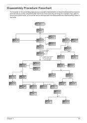
..., group the screws with the corresponding components to scrape the cover. Chapter 3 61 Chapter 3 Machine Disassembly and Replacement This chapter contains step-by-step procedures on how to disassemble the notebook computer for the different components vary in size. When you need the following tools: T ... Small Philips screw driver T Philips screwdriver T Plastic flat head screw driver T Tweezers NOTE: The screws for maintenance and troubleshooting. To disassemble the computer, you remove the stripe cover, please be careful not to avoid mismatch when putting back the components.
..., group the screws with the corresponding components to scrape the cover. Chapter 3 61 Chapter 3 Machine Disassembly and Replacement This chapter contains step-by-step procedures on how to disassemble the notebook computer for the different components vary in size. When you need the following tools: T ... Small Philips screw driver T Philips screwdriver T Plastic flat head screw driver T Tweezers NOTE: The screws for maintenance and troubleshooting. To disassemble the computer, you remove the stripe cover, please be careful not to avoid mismatch when putting back the components.

Aspire 5050 / 3050 Service Guide
Page 70
Turn off the power to the system and all power and signal cables from the system. 3. Remove the battery pack. 62 Chapter 3 Unplug the AC adapter and all peripherals. 2. General Information Before You Begin Before proceeding with the disassembly procedure, make sure that you do the following: 1.
Turn off the power to the system and all power and signal cables from the system. 3. Remove the battery pack. 62 Chapter 3 Unplug the AC adapter and all peripherals. 2. General Information Before You Begin Before proceeding with the disassembly procedure, make sure that you do the following: 1.
Aspire 5050 / 3050 Service Guide
Page 71
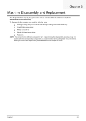
... that need to remove the system board, you must first remove the keyboard, then disassemble the inside assembly frame in that order. Disassembly Procedure Flowchart The flowchart on the succeeding page gives you a graphic representation on the entire disassembly sequence and instructs you on rear side H*3 HDD Cover Wireless LAN Card O*4 HDD Module...
... that need to remove the system board, you must first remove the keyboard, then disassemble the inside assembly frame in that order. Disassembly Procedure Flowchart The flowchart on the succeeding page gives you a graphic representation on the entire disassembly sequence and instructs you on rear side H*3 HDD Cover Wireless LAN Card O*4 HDD Module...
Aspire 5050 / 3050 Service Guide
Page 77
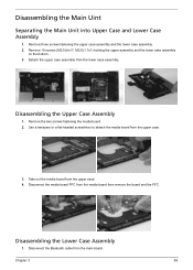
Remove 18 screws (M2.5L6x17; Remove the two screws fastening the media board. 2. Take out the media board from the main board. Disassembling the Upper Case Assembly 1. Disconnect the Bluetooth cable from the upper case. 4. M2.0L1.7x1) holding the upper assembly and the lower case assembly on .... 3. Remove three screws fastening the upper case assembly and the lower case assembly. 2. Detach the upper case assembly from the lower case assembly. Chapter 3 69 Disassembling the Main Uint Separating the Main Unit into Upper Case and Lower Case Assembly...
Remove 18 screws (M2.5L6x17; Remove the two screws fastening the media board. 2. Take out the media board from the main board. Disassembling the Upper Case Assembly 1. Disconnect the Bluetooth cable from the upper case. 4. M2.0L1.7x1) holding the upper assembly and the lower case assembly on .... 3. Remove three screws fastening the upper case assembly and the lower case assembly. 2. Detach the upper case assembly from the lower case assembly. Chapter 3 69 Disassembling the Main Uint Separating the Main Unit into Upper Case and Lower Case Assembly...

Aspire 5050 / 3050 Service Guide
Page 80
... bracket. 11. Then remove the right LCD bracket. 12. Then detach the LCD bezel from the LCD cover and disconnect the LVDS cable as shown. 2. Disassembling the LCD Module (with video camera) 1. Remove the six screw caps as shwon. 5. Remove the two screws holding the LCD assembly to the LCD cover...
... bracket. 11. Then remove the right LCD bracket. 12. Then detach the LCD bezel from the LCD cover and disconnect the LVDS cable as shown. 2. Disassembling the LCD Module (with video camera) 1. Remove the six screw caps as shwon. 5. Remove the two screws holding the LCD assembly to the LCD cover...

Aspire 5050 / 3050 Service Guide
Page 82
Disassembling the ODD Module 1. Remove the two screws holding the HDD bracket. 2. Then remove the ODD bracket. 3. Remove the HDD bracket. Detach the ODD bezel carefully. 74 Chapter 3 Remove two screws holding the ODD bracket. 2. Then remove two screws fastening the HDD braket on the other side. 3. Disassembling the External Modules Disassembling the HDD Module 1.
Disassembling the ODD Module 1. Remove the two screws holding the HDD bracket. 2. Then remove the ODD bracket. 3. Remove the HDD bracket. Detach the ODD bezel carefully. 74 Chapter 3 Remove two screws holding the ODD bracket. 2. Then remove two screws fastening the HDD braket on the other side. 3. Disassembling the External Modules Disassembling the HDD Module 1.


