
Aspire 4920 User Guide EN
Page 43
...pin 65 W AC adapter (for selected models) • 2.5-hour rapid charge system-off • 3.5-hour charge-in-use 3-pin 90 W AC adapter supporting Acer QuicCharge™ technology (for selected models): • 80% charge in 1 hour • 2-hour rapid charge system-off • 3-hour charge-in-use ...88-/89-/93-key keyboard, with inverted "T" cursor layout; 2.5 mm (minimum) key travel Seamless touchpad with 4-way scroll button 12 function keys, four cursor keys, two Windows® keys, hotkey...
...pin 65 W AC adapter (for selected models) • 2.5-hour rapid charge system-off • 3.5-hour charge-in-use 3-pin 90 W AC adapter supporting Acer QuicCharge™ technology (for selected models): • 80% charge in 1 hour • 2-hour rapid charge system-off • 3-hour charge-in-use ...88-/89-/93-key keyboard, with inverted "T" cursor layout; 2.5 mm (minimum) key travel Seamless touchpad with 4-way scroll button 12 function keys, four cursor keys, two Windows® keys, hotkey...
Service Guide
Page 8
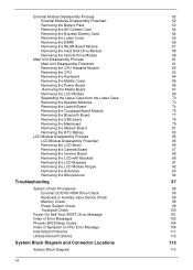
... the Modem Board Removing the RTC Battery LCD Module Disassembly Process LCD Module Disassembly Flowchart Removing the LCD Bezel Removing the Camera Board Removing the Inverter Board Removing the LCD with Brackets Removing the LCD Brackets Removing the LCD Module Hinges Removing the Antennas Removing the Microphones Troubleshooting System Check Procedures...
... the Modem Board Removing the RTC Battery LCD Module Disassembly Process LCD Module Disassembly Flowchart Removing the LCD Bezel Removing the Camera Board Removing the Inverter Board Removing the LCD with Brackets Removing the LCD Brackets Removing the LCD Module Hinges Removing the Antennas Removing the Microphones Troubleshooting System Check Procedures...
Service Guide
Page 12
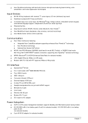
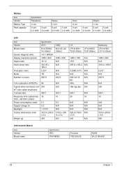
T Acer PureZone technology with two built-in stereo microphones featuring beam forming, echo cancellation, and noise suppression technologies Input Devices T 88-/89-/93-key keyboard, with inverted "T" cursor layout; 2.5 mm ...(minimum) key travel T Seamless touchpad with 4-way scroll button T 12 function keys, four cursor keys, two Windows® keys, hotkey controls, embedded numeric keypad, international language support, independent US and Euro dollar sign keys T Empowering Key T Easy-launch buttons: WLAN, Internet, email, Bluetooth, Acer Arcade™ T Acer...
T Acer PureZone technology with two built-in stereo microphones featuring beam forming, echo cancellation, and noise suppression technologies Input Devices T 88-/89-/93-key keyboard, with inverted "T" cursor layout; 2.5 mm ...(minimum) key travel T Seamless touchpad with 4-way scroll button T 12 function keys, four cursor keys, two Windows® keys, hotkey controls, embedded numeric keypad, international language support, independent US and Euro dollar sign keys T Empowering Key T Easy-launch buttons: WLAN, Internet, email, Bluetooth, Acer Arcade™ T Acer...
Service Guide
Page 46
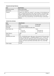
Keyboard and Input Devices Item Keyboard controller Model name Features Specification Winbond WPC8768L Acer FineTouch keyboard 5-degree curve, 88-/89- key, inverted "T" cursor layout, 2.5 mm (minimum) key travel, touchpad pointing device with 4-way scroll button or Acer BioProtect fingerprint reader supporting Acer Finger Nav 4-way control function, hotkey controls, embedded numeric keypad, multi-language support...
Keyboard and Input Devices Item Keyboard controller Model name Features Specification Winbond WPC8768L Acer FineTouch keyboard 5-degree curve, 88-/89- key, inverted "T" cursor layout, 2.5 mm (minimum) key travel, touchpad pointing device with 4-way scroll button or Acer BioProtect fingerprint reader supporting Acer Finger Nav 4-way control function, hotkey controls, embedded numeric keypad, multi-language support...
Service Guide
Page 48
... (6 N/A bit) 45% N/A 185 (typ.5p) 200 1280 x 800 N/A 303.4 x 189.6 0.237 N/A 262 K N/A 200 500:1 N/A 25 16 N/A N/A N/A N/A N/A N/A 320.0 x 199.0 N/A x 5.5 400 N/A 500:1 16 N/A N/A N/A 319.5 x205.5 x 5.5 390 LCD Inverter Board Item Vendor Model name Specification YEC YNV-W06S Foxconn T621240.02 RoHS VK.21189.406 38 Chapter 1
... (6 N/A bit) 45% N/A 185 (typ.5p) 200 1280 x 800 N/A 303.4 x 189.6 0.237 N/A 262 K N/A 200 500:1 N/A 25 16 N/A N/A N/A N/A N/A N/A 320.0 x 199.0 N/A x 5.5 400 N/A 500:1 16 N/A N/A N/A 319.5 x205.5 x 5.5 390 LCD Inverter Board Item Vendor Model name Specification YEC YNV-W06S Foxconn T621240.02 RoHS VK.21189.406 38 Chapter 1

Service Guide
Page 98
... the Keyboard" on page 62. 8. See "Removing the LCD Module" on page 56. 4. Carefully detach the aluminum foil tape from the inverter board. 88 Chapter 3 Remove the camera board. Removing the Inverter Board 1. See "Removing the DIMM" on page 68. 12. See "Removing the Middle Cover" on page 53. 2. See "Removing the...
... the Keyboard" on page 62. 8. See "Removing the LCD Module" on page 56. 4. Carefully detach the aluminum foil tape from the inverter board. 88 Chapter 3 Remove the camera board. Removing the Inverter Board 1. See "Removing the DIMM" on page 68. 12. See "Removing the Middle Cover" on page 53. 2. See "Removing the...

Service Guide
Page 99
... on page 53. 2. Step 1~2 Size (Quantity) M2.5 x L6 (2) Color Black Torque 3 kgf-cm 15. Disconnect the 2P cable from the inverter board, then disconnect the inverter board cable from its connector. 17. See "Removing the Battery Pack" on page 86. 13. See "Removing the CPU Heatsink Module" on page...Module" on page 64. 10. See "Removing the CPU" on page 56. 4. Turn the inverter board over. 16. Removing the LCD with Brackets 1. See "Removing the DIMM" on page 63. 9. See "Removing the Inverter Board" on page 68. 12. See "Removing the LCD Module" on page 88. See "...
... on page 53. 2. Step 1~2 Size (Quantity) M2.5 x L6 (2) Color Black Torque 3 kgf-cm 15. Disconnect the 2P cable from the inverter board, then disconnect the inverter board cable from its connector. 17. See "Removing the Battery Pack" on page 86. 13. See "Removing the CPU Heatsink Module" on page...Module" on page 64. 10. See "Removing the CPU" on page 56. 4. Turn the inverter board over. 16. Removing the LCD with Brackets 1. See "Removing the DIMM" on page 63. 9. See "Removing the Inverter Board" on page 68. 12. See "Removing the LCD Module" on page 88. See "...

Service Guide
Page 101
... Module" on page 55. 3. See "Removing the Middle Cover" on page 68. 12. See "Removing the LCD Module" on page 65. 11. See "Removing the Inverter Board" on page 63. 9. Removing the LCD Brackets 1. See "Removing the CPU" on page 88. 14. Detach the acetic tapes holding the FPC cable to...
... Module" on page 55. 3. See "Removing the Middle Cover" on page 68. 12. See "Removing the LCD Module" on page 65. 11. See "Removing the Inverter Board" on page 63. 9. Removing the LCD Brackets 1. See "Removing the CPU" on page 88. 14. Detach the acetic tapes holding the FPC cable to...

Service Guide
Page 102
... CPU Heatsink Module" on page 86. 13. Torque 1.6 kgf-cm Step 1~2 92 Size (Quantity) M2.5 x L6 (2) Color Black Torque 3.0 kgf-cm Chapter 3 See "Removing the Inverter Board" on page 58. 6. See "Removing the Hard Disk Drive Module" on page 88. 14. Remove the four screws (H) securing the left and right LCD...
... CPU Heatsink Module" on page 86. 13. Torque 1.6 kgf-cm Step 1~2 92 Size (Quantity) M2.5 x L6 (2) Color Black Torque 3.0 kgf-cm Chapter 3 See "Removing the Inverter Board" on page 58. 6. See "Removing the Hard Disk Drive Module" on page 88. 14. Remove the four screws (H) securing the left and right LCD...

Service Guide
Page 103
... the Battery Pack" on page 63. 9. See "Removing the CPU" on page 53. 2. See "Removing the LCD Module" on page 88. 14. See "Removing the Inverter Board" on page 68. 12. Remove the left and right hinges from the LCD back cover. See "Removing the Optical Drive Module" on page 89...
... the Battery Pack" on page 63. 9. See "Removing the CPU" on page 53. 2. See "Removing the LCD Module" on page 88. 14. See "Removing the Inverter Board" on page 68. 12. Remove the left and right hinges from the LCD back cover. See "Removing the Optical Drive Module" on page 89...

Service Guide
Page 104
... Drive Module" on page 62. 8. See "Removing the CPU Heatsink Module" on page 58. 6. See "Removing the CPU" on page 88. 14. See "Removing the Inverter Board" on page 63. 9. See "Removing the Keyboard" on page 65. 11. Carefully remove the microphone cables from underneath the adhesive aluminum foil. 94 Chapter...
... Drive Module" on page 62. 8. See "Removing the CPU Heatsink Module" on page 58. 6. See "Removing the CPU" on page 88. 14. See "Removing the Inverter Board" on page 63. 9. See "Removing the Keyboard" on page 65. 11. Carefully remove the microphone cables from underneath the adhesive aluminum foil. 94 Chapter...
Service Guide
Page 112
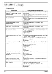
...T Run the BIOS Setup Utility to reconfigure the system time, then reboot system. T Reconnect the LCD connector T Hard disk drive T LCD cable T LCD inverter board T LCD T Mainboard T Reconnect the LCD connectors. T Run "Load Setup Defaults" in BIOS Setup Utility. T Run the BIOS Setup Utility to reconfigure...- T Mainboard T Run the BIOS Setup Utility to check if the fixed disk and drive A are properly identified. T LCD cable T LCD inverter board T LCD T Mainboard T Ensure every connector is connected tightly and correctly. But you can see POST on LCD during POST. Power-on ...
...T Run the BIOS Setup Utility to reconfigure the system time, then reboot system. T Reconnect the LCD connector T Hard disk drive T LCD cable T LCD inverter board T LCD T Mainboard T Reconnect the LCD connectors. T Run "Load Setup Defaults" in BIOS Setup Utility. T Run the BIOS Setup Utility to reconfigure...- T Mainboard T Run the BIOS Setup Utility to check if the fixed disk and drive A are properly identified. T LCD cable T LCD inverter board T LCD T Mainboard T Ensure every connector is connected tightly and correctly. But you can see POST on LCD during POST. Power-on ...

Service Guide
Page 113
... pack and power adapter). T Reconnect the LCD connector T Hard disk drive T LCD inverter ID T LCD cable T LCD Inverter board T LCD T Mainboard No beep, power-on indicator turns on and a T Ensure every connector is blank. T LCD inverter ID T LCD cable T LCD inverter board T LCD T Mainboard No beep, power-on indicator turns on and LCD is...
... pack and power adapter). T Reconnect the LCD connector T Hard disk drive T LCD inverter ID T LCD cable T LCD Inverter board T LCD T Mainboard No beep, power-on indicator turns on and a T Ensure every connector is blank. T LCD inverter ID T LCD cable T LCD inverter board T LCD T Mainboard No beep, power-on indicator turns on and LCD is...
Service Guide
Page 118
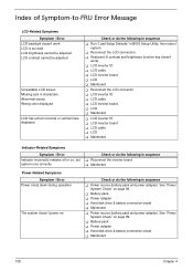
See "Power System Check" on . T LCD inverter ID T LCD cable T LCD inverter board T LCD T Mainboard T Reconnect the LCD connector T LCD inverter ID T LCD cable T LCD inverter board T LCD T Mainboard T LCD inverter ID T LCD inverter board T LCD cable T LCD T Mainboard Indicator-Related Symptoms Symptom / Error Indicator ... pack and power adapter). Check or do the following in sequence T Run "Load Setup Defaults" in sequence T Reconnect the inverter board. T Mainboard Power-Related Symptoms Symptom / Error Power shuts down during operation The system doesn't power-on page 99. ...
See "Power System Check" on . T LCD inverter ID T LCD cable T LCD inverter board T LCD T Mainboard T Reconnect the LCD connector T LCD inverter ID T LCD cable T LCD inverter board T LCD T Mainboard T LCD inverter ID T LCD inverter board T LCD cable T LCD T Mainboard Indicator-Related Symptoms Symptom / Error Indicator ... pack and power adapter). Check or do the following in sequence T Run "Load Setup Defaults" in sequence T Reconnect the inverter board. T Mainboard Power-Related Symptoms Symptom / Error Power shuts down during operation The system doesn't power-on page 99. ...


