Aspire 4920 User Guide EN
Page 5
... a distinct change in damage and will not occur at temperatures below 0°C (32°F) or above 40°C (104°F). Do not pierce, open or disassemble the battery. Do not use it to replace the power cord set, make sure that may result in performance, indicating a need to temperatures over 60...
... a distinct change in damage and will not occur at temperatures below 0°C (32°F) or above 40°C (104°F). Do not pierce, open or disassemble the battery. Do not use it to replace the power cord set, make sure that may result in performance, indicating a need to temperatures over 60...
Aspire 4920 User Guide EN
Page 6
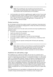
...in bodily injury or even death. They include below freezing. Warning! Batteries may damage the battery or the connecting object. Use only Acer approved batteries, and recharge your device in any charger or battery that which could cause an explosion or fire resulting in fuel depots...when disposing of used batteries. Please recycle when possible. chemical plants; Replacing the battery pack The notebook uses lithium batteries. Do not disassemble or dispose of them away from the battery, which came bundled with the same type as that is left in hot or cold places...
...in bodily injury or even death. They include below freezing. Warning! Batteries may damage the battery or the connecting object. Use only Acer approved batteries, and recharge your device in any charger or battery that which could cause an explosion or fire resulting in fuel depots...when disposing of used batteries. Please recycle when possible. chemical plants; Replacing the battery pack The notebook uses lithium batteries. Do not disassemble or dispose of them away from the battery, which came bundled with the same type as that is left in hot or cold places...

Aspire 4920 User Guide EN
Page 103
... used with high-precision manufacturing techniques. LAVATTAESSA OLET ALTTINA LASERSÅTEILYLLE. This has no effect on the drive. and 6,516,132." Reverse engineering or disassembly is a laser product. CLASS 1 LASER PRODUCT CAUTION: INVISIBLE LASER RADIATION WHEN OPEN. AVOID EXPOSURE TO BEAM. EVITTER TOUTE EXPOSITION AUX RAYONS. VARO! patents and other...
... used with high-precision manufacturing techniques. LAVATTAESSA OLET ALTTINA LASERSÅTEILYLLE. This has no effect on the drive. and 6,516,132." Reverse engineering or disassembly is a laser product. CLASS 1 LASER PRODUCT CAUTION: INVISIBLE LASER RADIATION WHEN OPEN. AVOID EXPOSURE TO BEAM. EVITTER TOUTE EXPOSITION AUX RAYONS. VARO! patents and other...
Service Guide
Page 7
...15 Hotkeys 16 Special Keys 17 Acer Empowering Technology 18 Empowering Technology Password 18 Acer eNet Management 19 Acer ePower Management 21 Acer eAudio Management 23 Acer ePresentation Management 24 Acer eDataSecurity Management 25 Acer eLock Management 26 Acer eRecovery Management 27 Acer eSettings Management 28 Windows Mobility Center...Menu 42 Main Menu 43 Security Menu 44 Boot Menu 46 Exit Menu 47 Machine Disassembly and Replacement 49 Disassembly Requirements 49 General Information 50 Pre-disassembly Instructions 50 Disassembly Process 51 vii
...15 Hotkeys 16 Special Keys 17 Acer Empowering Technology 18 Empowering Technology Password 18 Acer eNet Management 19 Acer ePower Management 21 Acer eAudio Management 23 Acer ePresentation Management 24 Acer eDataSecurity Management 25 Acer eLock Management 26 Acer eRecovery Management 27 Acer eSettings Management 28 Windows Mobility Center...Menu 42 Main Menu 43 Security Menu 44 Boot Menu 46 Exit Menu 47 Machine Disassembly and Replacement 49 Disassembly Requirements 49 General Information 50 Pre-disassembly Instructions 50 Disassembly Process 51 vii
Service Guide
Page 8
... the DIMM Removing the WLAN Board Module Removing the Hard Disk Drive Module Removing the Optical Drive Module Main Unit Disassembly Process Main Unit Disassembly Flowchart Removing the CPU Heatsink Module Removing the CPU Removing the Keyboard Removing the Middle Cover Removing the Power Board ... the Bluetooth Board Removing the USB board Removing the Mainboard Removing the Modem Board Removing the RTC Battery LCD Module Disassembly Process LCD Module Disassembly Flowchart Removing the LCD Bezel Removing the Camera Board Removing the Inverter Board Removing the LCD with Brackets Removing the ...
... the DIMM Removing the WLAN Board Module Removing the Hard Disk Drive Module Removing the Optical Drive Module Main Unit Disassembly Process Main Unit Disassembly Flowchart Removing the CPU Heatsink Module Removing the CPU Removing the Keyboard Removing the Middle Cover Removing the Power Board ... the Bluetooth Board Removing the USB board Removing the Mainboard Removing the Modem Board Removing the RTC Battery LCD Module Disassembly Process LCD Module Disassembly Flowchart Removing the LCD Bezel Removing the Camera Board Removing the Inverter Board Removing the LCD with Brackets Removing the ...

Service Guide
Page 59
... screwdriver T Plastic tweezers NOTE: The screws for maintenance and troubleshooting. Chapter 3 49 During the disassembly process, group the screws with the corresponding components to disassemble the notebook computer for the different components vary in size. Chapter 3 Machine Disassembly and Replacement This chapter contains step-by-step procedures on how to avoid mismatch when...
... screwdriver T Plastic tweezers NOTE: The screws for maintenance and troubleshooting. Chapter 3 49 During the disassembly process, group the screws with the corresponding components to disassemble the notebook computer for the different components vary in size. Chapter 3 Machine Disassembly and Replacement This chapter contains step-by-step procedures on how to avoid mismatch when...

Service Guide
Page 60
Place the system on page 53. 50 Chapter 3 See "Removing the Battery Pack" on a flat, stable surface. 4. Turn off the power to the system and all power and signal cables from the system. 3. Remove the battery pack. General Information Pre-disassembly Instructions Before proceeding with the disassembly procedure, make sure that you do the following: 1. Unplug the AC adapter and all peripherals. 2.
Place the system on page 53. 50 Chapter 3 See "Removing the Battery Pack" on a flat, stable surface. 4. Turn off the power to the system and all power and signal cables from the system. 3. Remove the battery pack. General Information Pre-disassembly Instructions Before proceeding with the disassembly procedure, make sure that you do the following: 1. Unplug the AC adapter and all peripherals. 2.
Service Guide
Page 61
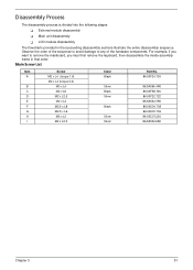
....736 86.00C07.220 86.9A552.6R0 Chapter 3 51 For example, if you must first remove the keyboard, then disassemble the inside assembly frame in the succeeding disassembly sections illustrate the entire disassembly sequence. Observe the order of the sequence to avoid damage to remove the mainboard, you want to any of the...
....736 86.00C07.220 86.9A552.6R0 Chapter 3 51 For example, if you must first remove the keyboard, then disassemble the inside assembly frame in the succeeding disassembly sections illustrate the entire disassembly sequence. Observe the order of the sequence to avoid damage to remove the mainboard, you want to any of the...
Service Guide
Page 62
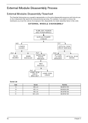
....5 Part No. 86.00F24.724 86.9A554.4R0 86.00F58.726 86.00F22.722 52 Chapter 3 External Module Disassembly Process External Modules Disassembly Flowchart The flowchart below gives you a graphic representation on the entire disassembly sequence and instructs you on the components that need to remove the mainboard, you want to be removed...
....5 Part No. 86.00F24.724 86.9A554.4R0 86.00F58.726 86.00F22.722 52 Chapter 3 External Module Disassembly Process External Modules Disassembly Flowchart The flowchart below gives you a graphic representation on the entire disassembly sequence and instructs you on the components that need to remove the mainboard, you want to be removed...
Service Guide
Page 71
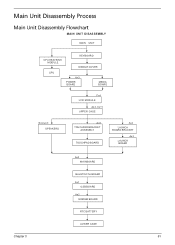
Main Unit Disassembly Process Main Unit Disassembly Flowchart MAIN UNIT DISASSEMBLY MAIN UNIT CPU HEATSINK MODULE CPU KEYBOARD MIDDLE COVER Ax3 POWER BOARD MEDIA BOARD Fx4 LCD MODULE Ax3, Cx11 UPPER CASE Screwx3 SPEAKERS Ax2 TOUCHPAD BRACKET ASSEMBLY TOUCHPAD BOARD Ax4 LAUNCH BOARD BRACKET Ax3 LAUNCH BOARD Ax2 MAINBOARD BLUETOOTH BOARD Ax1 USB BOARD Ax2 MODEM BOARD RTC BATTERY LOWER CASE Chapter 3 61
Main Unit Disassembly Process Main Unit Disassembly Flowchart MAIN UNIT DISASSEMBLY MAIN UNIT CPU HEATSINK MODULE CPU KEYBOARD MIDDLE COVER Ax3 POWER BOARD MEDIA BOARD Fx4 LCD MODULE Ax3, Cx11 UPPER CASE Screwx3 SPEAKERS Ax2 TOUCHPAD BRACKET ASSEMBLY TOUCHPAD BOARD Ax4 LAUNCH BOARD BRACKET Ax3 LAUNCH BOARD Ax2 MAINBOARD BLUETOOTH BOARD Ax1 USB BOARD Ax2 MODEM BOARD RTC BATTERY LOWER CASE Chapter 3 61
Service Guide
Page 107
Chapter 4 97 Verify the symptoms by attempting to test only Acer products. T There are no burned or heated components. If any power sources when performing an assembly or disassembly procedures. 4. Do not use any problems occur, you can give false errors and invalid system responses.... the diagnostic tests or repeating the same operation. 3. Chapter 4 Troubleshooting Use the following visual inspection before you continue. Non-Acer products, prototype cards, or modified options can perform the following procedure as possible. 2. Obtain the failing symptoms in as much...
Chapter 4 97 Verify the symptoms by attempting to test only Acer products. T There are no burned or heated components. If any power sources when performing an assembly or disassembly procedures. 4. Do not use any problems occur, you can give false errors and invalid system responses.... the diagnostic tests or repeating the same operation. 3. Chapter 4 Troubleshooting Use the following visual inspection before you continue. Non-Acer products, prototype cards, or modified options can perform the following procedure as possible. 2. Obtain the failing symptoms in as much...


