Acer Aspire 4350, 4750, 4750G, 4750Z Service Guide
Page 7
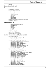
Table of Contents Features 1 System Specifications 1 1 System Block Diagram 4 Your Acer Notebook tour 5 Top view 5 Hotkeys 6 Closed front view 7 Rear view 7 Left view 7 Right view 9 Base... 24 Boot 28 Exit 29 BIOS Flash Utility 30 Remove HDD Password 31 Disassembly Requirements 33 Machine Disassembly and Replacement 33 General Information 34 Pre-disassembly Instructions 34 Disassembly Process 34 External Module Disassembly Process 35 External Modules Disassembly ...Main Board 55 Removing the Heatsink Module 58 Removing the CPU 60 Removing the LCD Module 61 LCD Module Disassembly Process 64 VII
Table of Contents Features 1 System Specifications 1 1 System Block Diagram 4 Your Acer Notebook tour 5 Top view 5 Hotkeys 6 Closed front view 7 Rear view 7 Left view 7 Right view 9 Base... 24 Boot 28 Exit 29 BIOS Flash Utility 30 Remove HDD Password 31 Disassembly Requirements 33 Machine Disassembly and Replacement 33 General Information 34 Pre-disassembly Instructions 34 Disassembly Process 34 External Module Disassembly Process 35 External Modules Disassembly ...Main Board 55 Removing the Heatsink Module 58 Removing the CPU 60 Removing the LCD Module 61 LCD Module Disassembly Process 64 VII
Acer Aspire 4350, 4750, 4750G, 4750Z Service Guide
Page 8
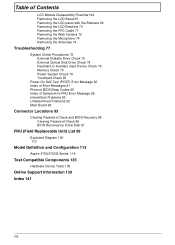
... Disassembly Flowchart 64 Removing the LCD Bezel 65 Removing the LCD panel with the Brackets 66 Removing the LCD Brackets 70 Removing the FPC Cable 71 Removing the Web Camera 72 Removing the Microphone 74 Removing the Antennas 74 Troubleshooting 77 System Check ...Clearing Password Check and BIOS Recovery 96 Clearing Password Check 96 BIOS Recovery by Crisis Disk 97 FRU (Field Replaceable Unit) List 99 Exploded Diagram 100 113 Model Definition and Configuration 113 Aspire 4750/4750G Series 114 Test Compatible Components 135 Hardware Device Tests 136 Online Support Information 139 Index 141 VIII
... Disassembly Flowchart 64 Removing the LCD Bezel 65 Removing the LCD panel with the Brackets 66 Removing the LCD Brackets 70 Removing the FPC Cable 71 Removing the Web Camera 72 Removing the Microphone 74 Removing the Antennas 74 Troubleshooting 77 System Check ...Clearing Password Check and BIOS Recovery 96 Clearing Password Check 96 BIOS Recovery by Crisis Disk 97 FRU (Field Replaceable Unit) List 99 Exploded Diagram 100 113 Model Definition and Configuration 113 Aspire 4750/4750G Series 114 Test Compatible Components 135 Hardware Device Tests 136 Online Support Information 139 Index 141 VIII
Acer Aspire 4350, 4750, 4750G, 4750Z Service Guide
Page 83
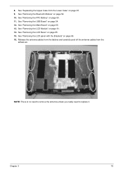
.... Release the antenna cables from the latches and carefully peel off the antenna cables from the Lower Case" on page 65. 15. See "Removing the LCD Bezel" on page 45. 9. See "Separating the Upper Case from the adhesives. See "Removing the Main Board" on page 52. 10. Chapter 3 75 NOTE: ...There is no need to remove the antenna unless you really need to replace it. 8. See "Removing the Bluetooth Module" on page 55. 13. See "Removing the LCD Module" on page 54. 12. See "Removing the USB Board" on page 61. 14.
.... Release the antenna cables from the latches and carefully peel off the antenna cables from the Lower Case" on page 65. 15. See "Removing the LCD Bezel" on page 45. 9. See "Separating the Upper Case from the adhesives. See "Removing the Main Board" on page 52. 10. Chapter 3 75 NOTE: ...There is no need to remove the antenna unless you really need to replace it. 8. See "Removing the Bluetooth Module" on page 55. 13. See "Removing the LCD Module" on page 54. 12. See "Removing the USB Board" on page 61. 14.
Acer Aspire 4350, 4750, 4750G, 4750Z Service Guide
Page 100
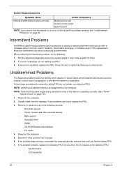
...Power System Check" on the computer. 5. NOTE: Verify that the power supply being used at the time of the following devices: • Non-Acer devices • Printer, mouse, and other external devices • Battery pack • Hard disk drive • DIMM • CD-ROM/Diskette... drive Module • PC Cards 4. Power-on page 79.): 1. Do not replace a non-defective FRU: • System board • LCD assembly 92 Chapter 4 Intermittent Problems Intermittent system hang problems can be considered only when a recurring problem exists. If no ...
...Power System Check" on the computer. 5. NOTE: Verify that the power supply being used at the time of the following devices: • Non-Acer devices • Printer, mouse, and other external devices • Battery pack • Hard disk drive • DIMM • CD-ROM/Diskette... drive Module • PC Cards 4. Power-on page 79.): 1. Do not replace a non-defective FRU: • System board • LCD assembly 92 Chapter 4 Intermittent Problems Intermittent system hang problems can be considered only when a recurring problem exists. If no ...
Acer Aspire 4350, 4750, 4750G, 4750Z Service Guide
Page 149
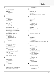
...42 display hotkeys 6 E External CD-ROM Drive Check 78 External Module Disassembly Index Flowchart 35 F Flash Utility 30 front view 7 FRU (Field Replaceable Unit) List 99 H Hard disk 13 HDD 13 HDD1 module removing 39 Hibernation mode hotkey 6 hotkeys 6 HW Gap position 96 I Intermittent ...Problems 92 K Keyboard 16 keyboard hotkeys 6 Keyboard or Auxiliary Input Device Check 78 L LCD bezel removing 65 LCD Brackets removing 70 LCD Module Disassembly Flowchart 64 LCD with the brackets removing 66 left speaker removing 54 left view 7 Locations connectors 93 M Main Screw List ...
...42 display hotkeys 6 E External CD-ROM Drive Check 78 External Module Disassembly Index Flowchart 35 F Flash Utility 30 front view 7 FRU (Field Replaceable Unit) List 99 H Hard disk 13 HDD 13 HDD1 module removing 39 Hibernation mode hotkey 6 hotkeys 6 HW Gap position 96 I Intermittent ...Problems 92 K Keyboard 16 keyboard hotkeys 6 Keyboard or Auxiliary Input Device Check 78 L LCD bezel removing 65 LCD Brackets removing 70 LCD Module Disassembly Flowchart 64 LCD with the brackets removing 66 left speaker removing 54 left view 7 Locations connectors 93 M Main Screw List ...


