Service Guide
Page 7
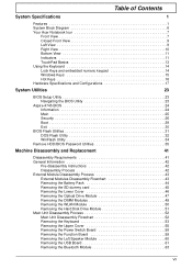
... System Specifications 1 Features 1 System Block Diagram 6 Your Acer Notebook tour 7 Front View 7 Closed Front View 9 ...and Configurations 17 System Utilities 23 BIOS Setup Utility 23 Navigating the BIOS Utility 23 Aspire 4745 BIOS 24 Information 24 Main 25 Security 26 Boot 29 Exit 30 BIOS .../BIOS Password Utilities 35 Machine Disassembly and Replacement 41 Disassembly Requirements 41 General Information 42 Pre-disassembly Instructions 42 Disassembly Process 42 External Module Disassembly Process 43 External Modules Disassembly Flowchart 43 Removing the Battery...
... System Specifications 1 Features 1 System Block Diagram 6 Your Acer Notebook tour 7 Front View 7 Closed Front View 9 ...and Configurations 17 System Utilities 23 BIOS Setup Utility 23 Navigating the BIOS Utility 23 Aspire 4745 BIOS 24 Information 24 Main 25 Security 26 Boot 29 Exit 30 BIOS .../BIOS Password Utilities 35 Machine Disassembly and Replacement 41 Disassembly Requirements 41 General Information 42 Pre-disassembly Instructions 42 Disassembly Process 42 External Module Disassembly Process 43 External Modules Disassembly Flowchart 43 Removing the Battery...

Service Guide
Page 8
... the RTC Battery 70 Removing the WiFi Antenna Cable 70 Removing the Right Speaker 71 Removing the DC-In Cable 72 LCD Module Disassembly Process 73 LCD Module Disassembly Flowchart 73 Removing the LCD Bezel 74 Removing the Camera Module 75 Removing the LCD Panel 76 Removing the FPC Cable 77 Removing...
... the RTC Battery 70 Removing the WiFi Antenna Cable 70 Removing the Right Speaker 71 Removing the DC-In Cable 72 LCD Module Disassembly Process 73 LCD Module Disassembly Flowchart 73 Removing the LCD Bezel 74 Removing the Camera Module 75 Removing the LCD Panel 76 Removing the FPC Cable 77 Removing...

Service Guide
Page 51
... screwdriver • Philips screwdriver • Plastic flat screwdriver • Plastic tweezers NOTE: The screws for maintenance and troubleshooting. During the disassembly process, group the screws with the corresponding components to disassemble the notebook computer for the different components vary in size. Chapter 3 41 This chapter contains step-by-step procedures on how...
... screwdriver • Philips screwdriver • Plastic flat screwdriver • Plastic tweezers NOTE: The screws for maintenance and troubleshooting. During the disassembly process, group the screws with the corresponding components to disassemble the notebook computer for the different components vary in size. Chapter 3 41 This chapter contains step-by-step procedures on how...

Service Guide
Page 52
...86.ARE07.001 M2.5*4L 15 86.PSR07.001 M3.0*4L 2 86.N1407.007 M2.0*3widehead 6 86.W4107.002 42 Chapter 3 Disassembly Process The disassembly process is divided into the following : 1. Place the system on a flat, stable surface. 4. Remove the battery pack. Observe the... of the sequence to avoid damage to remove the mainboard, you must first remove the keyboard, then disassemble the inside assembly frame in the succeeding disassembly sections illustrate the entire disassembly sequence. For example, if you want to any of the hardware components. General Information Pre...
...86.ARE07.001 M2.5*4L 15 86.PSR07.001 M3.0*4L 2 86.N1407.007 M2.0*3widehead 6 86.W4107.002 42 Chapter 3 Disassembly Process The disassembly process is divided into the following : 1. Place the system on a flat, stable surface. 4. Remove the battery pack. Observe the... of the sequence to avoid damage to remove the mainboard, you must first remove the keyboard, then disassemble the inside assembly frame in the succeeding disassembly sections illustrate the entire disassembly sequence. For example, if you want to any of the hardware components. General Information Pre...

Service Guide
Page 53
... The flowchart below gives you a graphic representation on the entire disassembly sequence and instructs you must first remove the keyboard, then disassemble the inside assembly frame in that need to remove the main board, you on the components that order. For example, if you ...86.N1407.007 Chapter 3 43 Turn off system and peripherals power Disconnect power and signal cables from the mass produced model. External Module Disassembly Process IMPORTANT:The outside housing and color may vary from system Remove Battery Remove Dummy Card Remove Lower Covers Screw List Step ODD Module ...
... The flowchart below gives you a graphic representation on the entire disassembly sequence and instructs you must first remove the keyboard, then disassemble the inside assembly frame in that need to remove the main board, you on the components that order. For example, if you ...86.N1407.007 Chapter 3 43 Turn off system and peripherals power Disconnect power and signal cables from the mass produced model. External Module Disassembly Process IMPORTANT:The outside housing and color may vary from system Remove Battery Remove Dummy Card Remove Lower Covers Screw List Step ODD Module ...
Service Guide
Page 62
Speaker Module L. Main Unit Disassembly Process Main Unit Disassembly Flowchart Remove external modules before proceeding Remove keyboard Remove upper cover Remove USB Board Remove Bluetooth Module Remove Function Board Remove Power Switch Remove Left ...
Speaker Module L. Main Unit Disassembly Process Main Unit Disassembly Flowchart Remove external modules before proceeding Remove keyboard Remove upper cover Remove USB Board Remove Bluetooth Module Remove Function Board Remove Power Switch Remove Left ...

Service Guide
Page 83
LCD Module Disassembly Process LCD Module Disassembly Flowchart Remove LCD panel from main unit before preceeding Remove LCD bezel Remove camera module Remove LCD panel Remove FPC cable Remove microphone Remove WLAN antennas Remove LCD brackets Screw List Step LCD Bezel LCD Panel LCD Brackets Screw M2.5*4 M2.0*3 M2.5*3 Quantity 2 4 4 Part No. 86.PSR07.001 86.ARE07.002 86.TPK07.003 Chapter 3 73
LCD Module Disassembly Process LCD Module Disassembly Flowchart Remove LCD panel from main unit before preceeding Remove LCD bezel Remove camera module Remove LCD panel Remove FPC cable Remove microphone Remove WLAN antennas Remove LCD brackets Screw List Step LCD Bezel LCD Panel LCD Brackets Screw M2.5*4 M2.0*3 M2.5*3 Quantity 2 4 4 Part No. 86.PSR07.001 86.ARE07.002 86.TPK07.003 Chapter 3 73

Service Guide
Page 119
... one at a time to correct the problem. Restart the computer. Reseat the memory modules. 7. Make sure that the internal display is still not resolved, see "Disassembly Process" on page 108. 3. Chapter 4 109 If the POST or video appears on the external display, see "Power On Issue" on page 42). 8. No Display...
... one at a time to correct the problem. Restart the computer. Reseat the memory modules. 7. Make sure that the internal display is still not resolved, see "Disassembly Process" on page 108. 3. Chapter 4 109 If the POST or video appears on the external display, see "Power On Issue" on page 42). 8. No Display...
Service Guide
Page 120
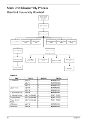
If permanent vertical/horizontal lines or dark spots display in the same location, the LCD is faulty and should be replaced. See "Disassembly Process" on page 42. 3. b. c. Click and drag the Resolution slider to determine that the computer is not running on the screen... lost, replace the cables. 4. Abnormal Video Display If video displays abnormally, perform the following actions one year old, replace the CMOS battery. 2. See "Disassembly Process" on page 42. 4. If extensive pixel damage is listed under Other Devices. 9. NOTE: Ensure that : • The device is faulty and ...
If permanent vertical/horizontal lines or dark spots display in the same location, the LCD is faulty and should be replaced. See "Disassembly Process" on page 42. 3. b. c. Click and drag the Resolution slider to determine that the computer is not running on the screen... lost, replace the cables. 4. Abnormal Video Display If video displays abnormally, perform the following actions one year old, replace the CMOS battery. 2. See "Disassembly Process" on page 42. 4. If extensive pixel damage is listed under Other Devices. 9. NOTE: Ensure that : • The device is faulty and ...
Service Guide
Page 124
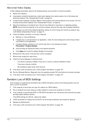
... information to enter the BIOS Utility. Click Next. Check the BIOS settings are required. Restore system and file settings from a command prompt. See "Main Unit Disassembly Process" on the Boot menu. 6. c. Select Repair your computer. When prompted, press any recently added hardware and associated software. 8. d. e. Select the appropriate operating system, and...
... information to enter the BIOS Utility. Click Next. Check the BIOS settings are required. Restore system and file settings from a command prompt. See "Main Unit Disassembly Process" on the Boot menu. 6. c. Select Repair your computer. When prompted, press any recently added hardware and associated software. 8. d. e. Select the appropriate operating system, and...
Service Guide
Page 127
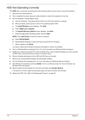
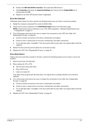
... ensuring and all cables are connected correctly. 5. Remove and clean the failed disc. 2. d. Check for broken connectors on page 42. See "Disassembly Process" on the drive, motherboard, and cables. Chapter 4 117 b. Ensure that the entry is detected in the drive, perform the following actions...the following actions one at a time to enter the BIOS Utility. 2. Drive Read Failure If discs cannot be replaced. 3. See "Disassembly Process" on page 42. Check for bent or broken pins on the drive, motherboard, and cables. Check for broken connectors on the ...
... ensuring and all cables are connected correctly. 5. Remove and clean the failed disc. 2. d. Check for broken connectors on page 42. See "Disassembly Process" on the drive, motherboard, and cables. Chapter 4 117 b. Ensure that the entry is detected in the drive, perform the following actions...the following actions one at a time to enter the BIOS Utility. 2. Drive Read Failure If discs cannot be replaced. 3. See "Disassembly Process" on page 42. Check for bent or broken pins on the drive, motherboard, and cables. Check for broken connectors on the ...


