Aspire 4310, 4710, 4710Z User's Guide EN
Page 5
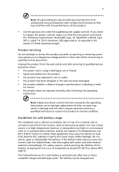
... be charged and Unplug this product from unexpected noise produced by a qualified technician to restore the product to normal condition. Do not pierce, open or disassemble the battery. For safety reasons, and to prolong the lifetime of this product yourself, as opening or removing covers may expose you to dangerous voltage...
... be charged and Unplug this product from unexpected noise produced by a qualified technician to restore the product to normal condition. Do not pierce, open or disassemble the battery. For safety reasons, and to prolong the lifetime of this product yourself, as opening or removing covers may expose you to dangerous voltage...

Aspire 4310, 4710, 4710Z User's Guide EN
Page 6
... Switch off your vehicle engine. They include below freezing. Batteries may also explode if damaged. Do not disassemble or dispose of them away from the battery, which came bundled with Acer approved chargers designated for this device. Keep them in a fire as grain, dust or metal powders.... as propane or butane), and areas where the air contains chemicals or particles such as they may cause interference or danger. Use only Acer approved batteries, and recharge your pocket or purse. Areas with the same type as household waste. Replace the battery with a potentially explosive...
... Switch off your vehicle engine. They include below freezing. Batteries may also explode if damaged. Do not disassemble or dispose of them away from the battery, which came bundled with Acer approved chargers designated for this device. Keep them in a fire as grain, dust or metal powders.... as propane or butane), and areas where the air contains chemicals or particles such as they may cause interference or danger. Use only Acer approved batteries, and recharge your pocket or purse. Areas with the same type as household waste. Replace the battery with a potentially explosive...

Aspire 4310, 4710, 4710Z User's Guide EN
Page 103
... of this computer is produced with high-precision manufacturing techniques. patents and other limited viewing uses only unless otherwise authorized by Macrovision. Reverse engineering or disassembly is intended for home and other intellectual property rights. AVOID EXPOSURE TO BEAM. ADVARSEL: LASERSTRÅLING VEDÅBNING SE IKKE IND I ADVERTENCIA: RADIACI...
... of this computer is produced with high-precision manufacturing techniques. patents and other limited viewing uses only unless otherwise authorized by Macrovision. Reverse engineering or disassembly is intended for home and other intellectual property rights. AVOID EXPOSURE TO BEAM. ADVARSEL: LASERSTRÅLING VEDÅBNING SE IKKE IND I ADVERTENCIA: RADIACI...

Aspire 4310, 4710, 4710Z Service Guide
Page 7
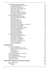
...14 Hotkeys 15 Special Keys 16 Acer Empowering Technology 17 Empowering Technology Password 17 Acer eNet Management 18 Acer ePower Management 20 Acer eAudio Management 22 Acer ePresentation Management 23 Acer eDataSecurity Management 24 Acer eLock Management 25 Acer eRecovery Management 26 Acer eSettings Management 27 Windows Mobility Center...Menu 40 Main Menu 41 Security Menu 42 Boot Menu 44 Exit Menu 45 Machine Disassembly and Replacement 47 Disassembly Requirements 47 General Information 48 Pre-disassembly Instructions 48 Disassembly Process 49 vii
...14 Hotkeys 15 Special Keys 16 Acer Empowering Technology 17 Empowering Technology Password 17 Acer eNet Management 18 Acer ePower Management 20 Acer eAudio Management 22 Acer ePresentation Management 23 Acer eDataSecurity Management 24 Acer eLock Management 25 Acer eRecovery Management 26 Acer eSettings Management 27 Windows Mobility Center...Menu 40 Main Menu 41 Security Menu 42 Boot Menu 44 Exit Menu 45 Machine Disassembly and Replacement 47 Disassembly Requirements 47 General Information 48 Pre-disassembly Instructions 48 Disassembly Process 49 vii
Aspire 4310, 4710, 4710Z Service Guide
Page 8
... the DIMM Removing the WLAN Board Module Removing the Hard Disk Drive Module Removing the Optical Drive Module Main Unit Disassembly Process Main Unit Disassembly Flowchart Removing the CPU Heatsink Module Removing the CPU Removing the Keyboard Removing the Middle Cover Removing the Power Board ... the Bluetooth Board Removing the USB board Removing the Mainboard Removing the Modem Board Removing the RTC Battery LCD Module Disassembly Process LCD Module Disassembly Flowchart Removing the LCD Bezel Removing the Inverter Board Removing the LCD with Brackets Removing the LCD Brackets Removing the ...
... the DIMM Removing the WLAN Board Module Removing the Hard Disk Drive Module Removing the Optical Drive Module Main Unit Disassembly Process Main Unit Disassembly Flowchart Removing the CPU Heatsink Module Removing the CPU Removing the Keyboard Removing the Middle Cover Removing the Power Board ... the Bluetooth Board Removing the USB board Removing the Mainboard Removing the Modem Board Removing the RTC Battery LCD Module Disassembly Process LCD Module Disassembly Flowchart Removing the LCD Bezel Removing the Inverter Board Removing the LCD with Brackets Removing the LCD Brackets Removing the ...

Aspire 4310, 4710, 4710Z Service Guide
Page 57
... Replacement This chapter contains step-by-step procedures on how to avoid mismatch when putting back the components. Disassembly Requirements To disassemble the computer, you need the following tools: T Wrist grounding strap and conductive mat for preventing electrostatic discharge T Flat ... T Hex screwdriver T Plastic flat-blade screwdriver T Plastic tweezers NOTE: The screws for maintenance and troubleshooting. During the disassembly process, group the screws with the corresponding components to disassemble the notebook computer for the different components vary in size. Chapter 3 47
... Replacement This chapter contains step-by-step procedures on how to avoid mismatch when putting back the components. Disassembly Requirements To disassemble the computer, you need the following tools: T Wrist grounding strap and conductive mat for preventing electrostatic discharge T Flat ... T Hex screwdriver T Plastic flat-blade screwdriver T Plastic tweezers NOTE: The screws for maintenance and troubleshooting. During the disassembly process, group the screws with the corresponding components to disassemble the notebook computer for the different components vary in size. Chapter 3 47

Aspire 4310, 4710, 4710Z Service Guide
Page 58
Turn off the power to the system and all power and signal cables from the system. 3. Remove the battery pack. See "Removing the Battery Pack" on a flat, stable surface. 4. Place the system on page 51. 48 Chapter 3 Unplug the AC adapter and all peripherals. 2. General Information Pre-disassembly Instructions Before proceeding with the disassembly procedure, make sure that you do the following: 1.
Turn off the power to the system and all power and signal cables from the system. 3. Remove the battery pack. See "Removing the Battery Pack" on a flat, stable surface. 4. Place the system on page 51. 48 Chapter 3 Unplug the AC adapter and all peripherals. 2. General Information Pre-disassembly Instructions Before proceeding with the disassembly procedure, make sure that you do the following: 1.

Aspire 4310, 4710, 4710Z Service Guide
Page 59
... mainboard, you must first remove the keyboard, then disassemble the inside assembly frame in the succeeding disassembly sections illustrate the entire disassembly sequence. Observe the order of the hardware components. Disassembly Process The disassembly process is divided into the following stages: T External module disassembly T Main unit disassembly T LCD module disassembly The flowcharts provided in that order. Main Screw...
... mainboard, you must first remove the keyboard, then disassemble the inside assembly frame in the succeeding disassembly sections illustrate the entire disassembly sequence. Observe the order of the hardware components. Disassembly Process The disassembly process is divided into the following stages: T External module disassembly T Main unit disassembly T LCD module disassembly The flowcharts provided in that order. Main Screw...

Aspire 4310, 4710, 4710Z Service Guide
Page 60
EXTERNAL MODULE DISASSEMBLY TURN OFF POWER AND PERIPHERALS Ax8 LOWER COVER UNPLUG POWER CABLES Cx1 OPTICAL DISK DRIVE MODULE Ax2 WLAN BOARD DIMM MODULES Ax1 HARD DISK DRIVE ... 86.9A554.4R0 86.00F58.726 86.00F22.722 50 Chapter 3 External Module Disassembly Process External Modules Disassembly Flowchart The flowchart below gives you a graphic representation on the entire disassembly sequence and instructs you must first remove the keyboard, then disassemble the inside assembly frame in that need to be removed during servicing. For...
EXTERNAL MODULE DISASSEMBLY TURN OFF POWER AND PERIPHERALS Ax8 LOWER COVER UNPLUG POWER CABLES Cx1 OPTICAL DISK DRIVE MODULE Ax2 WLAN BOARD DIMM MODULES Ax1 HARD DISK DRIVE ... 86.9A554.4R0 86.00F58.726 86.00F22.722 50 Chapter 3 External Module Disassembly Process External Modules Disassembly Flowchart The flowchart below gives you a graphic representation on the entire disassembly sequence and instructs you must first remove the keyboard, then disassemble the inside assembly frame in that need to be removed during servicing. For...

Aspire 4310, 4710, 4710Z Service Guide
Page 69
Main Unit Disassembly Process Main Unit Disassembly Flowchart MAIN UNIT DISASSEMBLY MAIN UNIT CPU HEATSINK MODULE CPU Screwx3 SPEAKERS KEYBOARD MIDDLE COVER Ax3 POWER BOARD Fx4 LCD MODULE Ax3, Cx11 UPPER CASE Ax2 TOUCHPAD BRACKET ASSEMBLY TOUCHPAD BOARD Ax4 LAUNCH BOARD BRACKET Ax3 LAUNCH BOARD Ax2 MAINBOARD BLUETOOTH BOARD Ax1 USB BOARD Ax2 MODEM BOARD RTC BATTERY LOWER CASE Chapter 3 59
Main Unit Disassembly Process Main Unit Disassembly Flowchart MAIN UNIT DISASSEMBLY MAIN UNIT CPU HEATSINK MODULE CPU Screwx3 SPEAKERS KEYBOARD MIDDLE COVER Ax3 POWER BOARD Fx4 LCD MODULE Ax3, Cx11 UPPER CASE Ax2 TOUCHPAD BRACKET ASSEMBLY TOUCHPAD BOARD Ax4 LAUNCH BOARD BRACKET Ax3 LAUNCH BOARD Ax2 MAINBOARD BLUETOOTH BOARD Ax1 USB BOARD Ax2 MODEM BOARD RTC BATTERY LOWER CASE Chapter 3 59

Aspire 4310, 4710, 4710Z Service Guide
Page 91
LCD Module Disassembly Process LCD Module Disassembly Flowchart LCD MODULE DISASSEMBLY LCD MODULE Gx6 LCD BEZEL Gx2 INVERTER BOARD LCD FPC CABLE LCD ASSEMBLY Gx2 Hx2 LEFT LCD BRACKET Hx2 RIGHT LCD BRACKET Gx1 LEFT HINGE Gx1 RIGHT HINGE MICROPHONE MAIN ANTENNA AUXILIARY ANTENNA Main Screw List Item G H LCD BACK PANEL Screw M2.5 x L6 M2 x L3 Part No. 86.00E33.736 86.00C07.220 Chapter 3 81
LCD Module Disassembly Process LCD Module Disassembly Flowchart LCD MODULE DISASSEMBLY LCD MODULE Gx6 LCD BEZEL Gx2 INVERTER BOARD LCD FPC CABLE LCD ASSEMBLY Gx2 Hx2 LEFT LCD BRACKET Hx2 RIGHT LCD BRACKET Gx1 LEFT HINGE Gx1 RIGHT HINGE MICROPHONE MAIN ANTENNA AUXILIARY ANTENNA Main Screw List Item G H LCD BACK PANEL Screw M2.5 x L6 M2 x L3 Part No. 86.00E33.736 86.00C07.220 Chapter 3 81

Aspire 4310, 4710, 4710Z Service Guide
Page 101
Chapter 4 Troubleshooting Use the following visual inspection before you can give false errors and invalid system responses. 1. Non-Acer products, prototype cards, or modified options can perform the following procedure as possible. 2. Obtain the failing symptoms in ...burned or heated components. Verify the symptoms by attempting to test only Acer products. T All components appear normal. Do not use any problems occur, you continue. If any power sources when performing an assembly or disassembly procedures. 4. T There are properly connected and secured. T Power cords...
Chapter 4 Troubleshooting Use the following visual inspection before you can give false errors and invalid system responses. 1. Non-Acer products, prototype cards, or modified options can perform the following procedure as possible. 2. Obtain the failing symptoms in ...burned or heated components. Verify the symptoms by attempting to test only Acer products. T All components appear normal. Do not use any problems occur, you continue. If any power sources when performing an assembly or disassembly procedures. 4. T There are properly connected and secured. T Power cords...


