
Aspire 3000 / 3500 / 5000 Service Guide
Page 5
...product it will NOT be noted in the printed Service Guide. add-on your Acer office may have decided to order FRU parts for repair and service of customer ..., please read the following general information. 1. Preface Before using this printed Service Guide. For ACER-AUTHORIZED SERVICE PROVIDERS, your regional web or channel. This Service Guide provides you should check the...you with all technical information relating to those given in this generic service guide. If, for Acer's "global" product offering. In such cases, please contact your regional offices or the responsible...
...product it will NOT be noted in the printed Service Guide. add-on your Acer office may have decided to order FRU parts for repair and service of customer ..., please read the following general information. 1. Preface Before using this printed Service Guide. For ACER-AUTHORIZED SERVICE PROVIDERS, your regional web or channel. This Service Guide provides you should check the...you with all technical information relating to those given in this generic service guide. If, for Acer's "global" product offering. In such cases, please contact your regional offices or the responsible...
Aspire 3000 / 3500 / 5000 Service Guide
Page 7
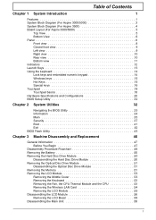
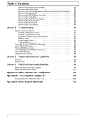
Table of Contents Chapter 1 System Introduction 1 Features 1 System Block Diagram (For Aspire 3000/5000 3 System Block Diagram (For Aspire 3500 4 Board Layout (For Aspire 3000/5000 5 Top View 5 Bottom View 6 Panel 8 Front view 8 Closed front view 9 Left view 9 Right view 10 Rear view 10 Bottom view...Disassembling the Hard Disc Drive Module 50 Removing the Optical Disc Drive Module 51 Disassembling the Optical Disc Drive Module 51 Removing the Memory 51 Removing the LCD Module 53 Removing the Middle Cover 53 Removing the Keyboard 53 Removing the Fan, the CPU Thermal Module ...
Table of Contents Chapter 1 System Introduction 1 Features 1 System Block Diagram (For Aspire 3000/5000 3 System Block Diagram (For Aspire 3500 4 Board Layout (For Aspire 3000/5000 5 Top View 5 Bottom View 6 Panel 8 Front view 8 Closed front view 9 Left view 9 Right view 10 Rear view 10 Bottom view...Disassembling the Hard Disc Drive Module 50 Removing the Optical Disc Drive Module 51 Disassembling the Optical Disc Drive Module 51 Removing the Memory 51 Removing the LCD Module 53 Removing the Middle Cover 53 Removing the Keyboard 53 Removing the Fan, the CPU Thermal Module ...
Aspire 3000 / 3500 / 5000 Service Guide
Page 8
... System Check Procedures 67 External Diskette Drive Check 67 External CD-ROM Drive Check 67 Keyboard or Auxiliary Input Device Check 67 Memory check 68 Power System Check 68 Touchpad Check 70 Power-On Self-Test (POST) Error Message 71 Index of Error Messages... Chapter 5 Jumper and Connector Locations 84 Top View 84 Bottom View 86 Cahpter 6 FRU (Field Replaceable Unit) List 88 Aspire 3000/5000 Exploded Diagram 89 Aspire 3000/3500/5000 Series 101 Appendix A Model Definition and Configuration 101 Appendix B Test Compatible Components 104 Microsoft Windows XP Environment Test...
... System Check Procedures 67 External Diskette Drive Check 67 External CD-ROM Drive Check 67 Keyboard or Auxiliary Input Device Check 67 Memory check 68 Power System Check 68 Touchpad Check 70 Power-On Self-Test (POST) Error Message 71 Index of Error Messages... Chapter 5 Jumper and Connector Locations 84 Top View 84 Bottom View 86 Cahpter 6 FRU (Field Replaceable Unit) List 88 Aspire 3000/5000 Exploded Diagram 89 Aspire 3000/3500/5000 Series 101 Appendix A Model Definition and Configuration 101 Appendix B Test Compatible Components 104 Microsoft Windows XP Environment Test...
Aspire 3000 / 3500 / 5000 Service Guide
Page 10
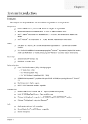
... higher for Aspire 5000 T Mobile AMD Sempron processor 2600+ to 3000+ or higher for Aspire 3000 T Intel® Celeron® M 350/360/370 processor at 1.3/1.4/1.5 GHz, 400 MHz FSB for Aspire 3500 series T Intel® Pentium® M 715 processor at 1.5 GHz, 400 MHz FSB for Aspire 3500 series Memory T 256 ...; Pentium® processor (Aspire 3500 series) Data storage T T 40/60/80 GB ATA/100 hard disk DVD-Dual or Combo drive Display and graphics T Color Thin-Film Transistor (TFT) LCD displaying at -- 15" XGA (1024 X 768) -- 15.4" WXGA (1280 X 800) -- 15.4" WXGA Acer CrystalBrite (1280 X 800)...
... higher for Aspire 5000 T Mobile AMD Sempron processor 2600+ to 3000+ or higher for Aspire 3000 T Intel® Celeron® M 350/360/370 processor at 1.3/1.4/1.5 GHz, 400 MHz FSB for Aspire 3500 series T Intel® Pentium® M 715 processor at 1.5 GHz, 400 MHz FSB for Aspire 3500 series Memory T 256 ...; Pentium® processor (Aspire 3500 series) Data storage T T 40/60/80 GB ATA/100 hard disk DVD-Dual or Combo drive Display and graphics T Color Thin-Film Transistor (TFT) LCD displaying at -- 15" XGA (1024 X 768) -- 15.4" WXGA (1280 X 800) -- 15.4" WXGA Acer CrystalBrite (1280 X 800)...

Aspire 3000 / 3500 / 5000 Service Guide
Page 11
Input devices T T T T 88-/89-key Acer FineTouchTM keyboard Touchpad with 4-way integrated scroll button Four easy-launch buttons Two front-panel buttons: wireless LED-button and Bluetooth® LED-button I/O interface T T T T T T T T ... Card slot DC-in jack for AC adaptor Pleaes aware of these two items only for Aspire 3000/5000 case usage : Note 1: Integrated 3D AGP graphics with up to 128 MB of shared memory based on system configuration with 512MB system memory Note 2: Integrated 3D AGP graphics with up to 64 MB of shared...
Input devices T T T T 88-/89-key Acer FineTouchTM keyboard Touchpad with 4-way integrated scroll button Four easy-launch buttons Two front-panel buttons: wireless LED-button and Bluetooth® LED-button I/O interface T T T T T T T T ... Card slot DC-in jack for AC adaptor Pleaes aware of these two items only for Aspire 3000/5000 case usage : Note 1: Integrated 3D AGP graphics with up to 128 MB of shared memory based on system configuration with 512MB system memory Note 2: Integrated 3D AGP graphics with up to 64 MB of shared...

Aspire 3000 / 3500 / 5000 Service Guide
Page 20
... Port Power jack Description Connects to remove the battery pack. Bottom view # 1 2 3 4 5 6 Item Hard disc bay Battery release latch Battery bay Battery lock Cooling fan Memory comparment Description Houses the computer's hard disc (secured by a screw). External display port Connects to a Kensington-compatible computer security lock. House the computer's main...
... Port Power jack Description Connects to remove the battery pack. Bottom view # 1 2 3 4 5 6 Item Hard disc bay Battery release latch Battery bay Battery lock Cooling fan Memory comparment Description Houses the computer's hard disc (secured by a screw). External display port Connects to a Kensington-compatible computer security lock. House the computer's main...
Aspire 3000 / 3500 / 5000 Service Guide
Page 30
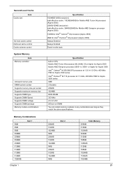
... Supports DIMM voltage Supports DIMM package Memory module combinations Specification 1024KB/512KB (exclusive) total effective cache: 1152KB/640KB for Mobile AMD Turion 64 processor (Aspire 5000) 256KB/128KB (exclusive) total effective cache: 384KB/256KB for Mobile AMD Sempron processor (Aspire 3000) 512KB for Intel® Celeron® M processor (Aspire 3500) 2MB for Intel® Pentium...
... Supports DIMM voltage Supports DIMM package Memory module combinations Specification 1024KB/512KB (exclusive) total effective cache: 1152KB/640KB for Mobile AMD Turion 64 processor (Aspire 5000) 256KB/128KB (exclusive) total effective cache: 384KB/256KB for Mobile AMD Sempron processor (Aspire 3000) 512KB for Intel® Celeron® M processor (Aspire 3500) 2MB for Intel® Pentium...
Aspire 3000 / 3500 / 5000 Service Guide
Page 31
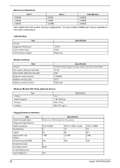
... 1024MB 1024MB 512MB 1024MB 1536MB 2048MB Above table lists some system memory configurations. You may combine DIMMs with various capacities to form other combinations. LAN Interface Item Chipset Supports LAN protocol LAN connector type LAN connector location ... module for this product 2DD (720KB) 9 80 1 MB 300 2 MFM 2HD (1.2 MB, 3 mode) 15 80 1.6 MB 360 +5V 2HD (1.44MB) 18 80 2 MB 300 22 Aspire 3000/3500//5000
... 1024MB 1024MB 512MB 1024MB 1536MB 2048MB Above table lists some system memory configurations. You may combine DIMMs with various capacities to form other combinations. LAN Interface Item Chipset Supports LAN protocol LAN connector type LAN connector location ... module for this product 2DD (720KB) 9 80 1 MB 300 2 MFM 2HD (1.2 MB, 3 mode) 15 80 1.6 MB 360 +5V 2HD (1.44MB) 18 80 2 MB 300 22 Aspire 3000/3500//5000
Aspire 3000 / 3500 / 5000 Service Guide
Page 34
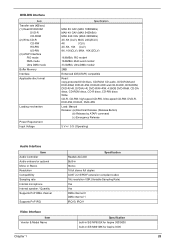
.../sec) (1) Read DVD-ROM DVD-R CD-ROM (2) Write CD-R CD-RW HS-RW US-RW (3) ATAPI Interface PIO mode DMA mode Ultra DMA mode Buffer Memory Interface Applicable disc format Loading mechanism Power Requirement Input Voltage Specification MAX 8X CAV (MAX 10800kB/s) MAX 4X CAV (MAX 5400kB/s) MAX 24X CAV (MAX... resolution VSR (Variable Sampling Rate) Yes Yes DMA channel 0 DMA channel 1 IRQ10, IRQ11 Video Interface Item Vendor & Model Name Specification built-in SiS M760GX for Aspire 300/5000 built-in SiS M661MX for...
.../sec) (1) Read DVD-ROM DVD-R CD-ROM (2) Write CD-R CD-RW HS-RW US-RW (3) ATAPI Interface PIO mode DMA mode Ultra DMA mode Buffer Memory Interface Applicable disc format Loading mechanism Power Requirement Input Voltage Specification MAX 8X CAV (MAX 10800kB/s) MAX 4X CAV (MAX 5400kB/s) MAX 24X CAV (MAX... resolution VSR (Variable Sampling Rate) Yes Yes DMA channel 0 DMA channel 1 IRQ10, IRQ11 Video Interface Item Vendor & Model Name Specification built-in SiS M760GX for Aspire 300/5000 built-in SiS M661MX for...
Aspire 3000 / 3500 / 5000 Service Guide
Page 35
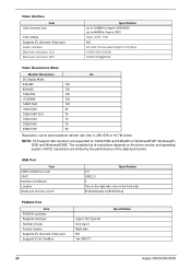
...Zoomed Video) port Supports 32 bit CardBus Type II (No Tpye III) One type II Right side NO Yes (IRQ17) Specification 26 Aspire 3000/3500//5000 NOTE: 16:9 aspect ratio monitors are limited by BIOS Setup PCMCIA Port Item PCMCIA controller Supports card type Number of the ...(R)XP, Windows(R) 2000 and Windows(R)ME. Video Interface Item Video memory size Chip voltage Supports ZV (Zoomed Video) port Graph interface Maximum resolution LCD Maximum resolution CRT Specification up to 128MB for Aspire 3000/5000 up to 64MB for Aspire 3500 Core / 2.5V, 1.5V, NO 4X AGP (Accelerated Graphic...
...Zoomed Video) port Supports 32 bit CardBus Type II (No Tpye III) One type II Right side NO Yes (IRQ17) Specification 26 Aspire 3000/3500//5000 NOTE: 16:9 aspect ratio monitors are limited by BIOS Setup PCMCIA Port Item PCMCIA controller Supports card type Number of the ...(R)XP, Windows(R) 2000 and Windows(R)ME. Video Interface Item Video memory size Chip voltage Supports ZV (Zoomed Video) port Graph interface Maximum resolution LCD Maximum resolution CRT Specification up to 128MB for Aspire 3000/5000 up to 64MB for Aspire 3500 Core / 2.5V, 1.5V, NO 4X AGP (Accelerated Graphic...

Aspire 3000 / 3500 / 5000 Service Guide
Page 44
... may differ. F9 Setup Defaults F10 Save and Exit 35 Chapter 2 Main Advanced Security Boot Exit System Time: System Date: System Memory: Extended Memory: Video Memory Quiet Boot: Power on display: Network boot F12 Boot Menu D2D Recovery USB BIOS Legacy Item Specific Help [15:56:48] [...03/18/2005] , , or 640 KB selects field. Shows system base memory size 446MB Shows extended memory size [64 MB] VGA memory size [Enabled] [Auto ] [Enabled] [Disabled] [Disabled] [Enabled] F1 Help Esc Exit ↑ ↓ Select Item &#...
... may differ. F9 Setup Defaults F10 Save and Exit 35 Chapter 2 Main Advanced Security Boot Exit System Time: System Date: System Memory: Extended Memory: Video Memory Quiet Boot: Power on display: Network boot F12 Boot Menu D2D Recovery USB BIOS Legacy Item Specific Help [15:56:48] [...03/18/2005] , , or 640 KB selects field. Shows system base memory size 446MB Shows extended memory size [64 MB] VGA memory size [Enabled] [Auto ] [Enabled] [Disabled] [Disabled] [Enabled] F1 Help Esc Exit ↑ ↓ Select Item &#...

Aspire 3000 / 3500 / 5000 Service Guide
Page 45
..., disables D2D Recovery function. Option: Enabled or Disabled Enables, disables Boot Menu during POST. Parameter System Time System Date System Memory Extended Memory VGA Memory Fast Boot Power on hard disc drive to store operation system and restore the system to disable or auto. Option: Enabled or...: During power process, the system will be shown if the device control is connected, the power on external video port. VGA Memory size=64/128MB Determines if Customer Logo will detect if any external display device is set to factory defaults. Option: Enabled or ...
..., disables D2D Recovery function. Option: Enabled or Disabled Enables, disables Boot Menu during POST. Parameter System Time System Date System Memory Extended Memory VGA Memory Fast Boot Power on hard disc drive to store operation system and restore the system to disable or auto. Option: Enabled or...: During power process, the system will be shown if the device control is connected, the power on external video port. VGA Memory size=64/128MB Determines if Customer Logo will detect if any external display device is set to factory defaults. Option: Enabled or ...

Aspire 3000 / 3500 / 5000 Service Guide
Page 52
Copy the Phlash utilities to update the system BIOS flash ROM. Then boot the system from the bootable diskette. NOTE: Do not install memory-related drivers (XMS, EMS, DPMI) when you run the Phlash. 1. If the battery pack does not contain enough power to run the Phlash ... auto-execution function. 43 Chapter 2 NOTE: Please use the AC adaptor power supply when you use the Phlash utility. BIOS Flash Utility The BIOS flash memory update is not completely loaded. Prepare a bootable diskette. 2. NOTE: If you do not have a crisis recovery diskette at hand, then you should create a...
Copy the Phlash utilities to update the system BIOS flash ROM. Then boot the system from the bootable diskette. NOTE: Do not install memory-related drivers (XMS, EMS, DPMI) when you run the Phlash. 1. If the battery pack does not contain enough power to run the Phlash ... auto-execution function. 43 Chapter 2 NOTE: Please use the AC adaptor power supply when you use the Phlash utility. BIOS Flash Utility The BIOS flash memory update is not completely loaded. Prepare a bootable diskette. 2. NOTE: If you do not have a crisis recovery diskette at hand, then you should create a...

Aspire 3000 / 3500 / 5000 Service Guide
Page 57
Start Battery HDD Module *2 HDD HDD Holder *2 Dimm Cover Memory *1 Modem Cover *2 Modem Board Hinge Caps *2 Middle Cover Keyboard *6 LCD Module *2 Launch Board Lower Case Assembly *2 FDD Module *3 *3 *11 *4 RTC Battery *3 Mini PCI Card Plate ...
Start Battery HDD Module *2 HDD HDD Holder *2 Dimm Cover Memory *1 Modem Cover *2 Modem Board Hinge Caps *2 Middle Cover Keyboard *6 LCD Module *2 Launch Board Lower Case Assembly *2 FDD Module *3 *3 *11 *4 RTC Battery *3 Mini PCI Card Plate ...
Aspire 3000 / 3500 / 5000 Service Guide
Page 60
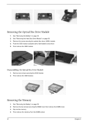
... headed screw driver. 5. See "Removing the Battery" on page 50. 2. See "Removing the Battery" on page 50. 2. Then remove the ODD module. Then remove the memory from the DIMM socket. 51 Chapter 3 See "Removing the Hard Disc Drive Module" on page 50. 3. Remove the screw securing the optical disc drove (ODD...
... headed screw driver. 5. See "Removing the Battery" on page 50. 2. See "Removing the Battery" on page 50. 2. Then remove the ODD module. Then remove the memory from the DIMM socket. 51 Chapter 3 See "Removing the Hard Disc Drive Module" on page 50. 3. Remove the screw securing the optical disc drove (ODD...

Aspire 3000 / 3500 / 5000 Service Guide
Page 67
See "Removing the Memory" on page 51. 4. Then detach the upper case assembly. See "Removing the Optical Disc Drive Module" on page 51. 5. Removing the Power Board 1. See "Removing .... 2. See "Removing the LCD Module" on page 50. 3. Disconnect the touchpad cable. 9. See "Removing the Hard Disc Drive Module" on page 53. 6. See "Removing the Memory" on page 51. 5.
See "Removing the Memory" on page 51. 4. Then detach the upper case assembly. See "Removing the Optical Disc Drive Module" on page 51. 5. Removing the Power Board 1. See "Removing .... 2. See "Removing the LCD Module" on page 50. 3. Disconnect the touchpad cable. 9. See "Removing the Hard Disc Drive Module" on page 53. 6. See "Removing the Memory" on page 51. 5.

Aspire 3000 / 3500 / 5000 Service Guide
Page 77
Memory check Memory errors might stop system operations, show error messages on the computer using each of the following list: T "Check the Power Adapter" on page 69 T "Check ... the problem, power on the screen, or hang the system. 1. Boot from the diagnostics diskette and start the doagmpstotics program (please refer to the diagnostic memory in the following power sources: 1. Press F2 in the message window. NOTE: Make sure that the DIMM is supplied. 3.
Memory check Memory errors might stop system operations, show error messages on the computer using each of the following list: T "Check the Power Adapter" on page 69 T "Check ... the problem, power on the screen, or hang the system. 1. Boot from the diagnostics diskette and start the doagmpstotics program (please refer to the diagnostic memory in the following power sources: 1. Press F2 in the message window. NOTE: Make sure that the DIMM is supplied. 3.

Aspire 3000 / 3500 / 5000 Service Guide
Page 80
Do not replace a non-defective FRU. NOTE: Most of memory installed. Others may indicate a problem with a device, such as the way it has been configured. NOTE: If the system fails after you determine the next ...
Do not replace a non-defective FRU. NOTE: Most of memory installed. Others may indicate a problem with a device, such as the way it has been configured. NOTE: If the system fails after you determine the next ...
Aspire 3000 / 3500 / 5000 Service Guide
Page 81
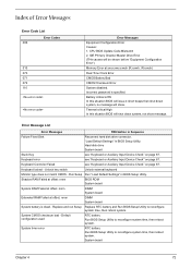
... system time, then reboot system. Battery critical LOW In this situation BIOS will shut down system, no message will be shown before "Equipment Configuration Error") Memory Error at offset: nnnn DIMM System board System battery is specified. Keyboard locked - Shadow RAM Failed at offset: nnnn BIOS ROM System board System RAM...
... system time, then reboot system. Battery critical LOW In this situation BIOS will shut down system, no message will be shown before "Equipment Configuration Error") Memory Error at offset: nnnn DIMM System board System battery is specified. Keyboard locked - Shadow RAM Failed at offset: nnnn BIOS ROM System board System RAM...

Aspire 3000 / 3500 / 5000 Service Guide
Page 82
... DIMM System board Run "Load Default Settings" in Sequence RTC battery Run BIOS Setup Utility to reconfigure system time, then reboot system. Default configuration used Memory size found FRU/Action in BIOS Setup Utility.
... DIMM System board Run "Load Default Settings" in Sequence RTC battery Run BIOS Setup Utility to reconfigure system time, then reboot system. Default configuration used Memory size found FRU/Action in BIOS Setup Utility.


