Aspire 1420P and 1820PT Service Guide
Page 7
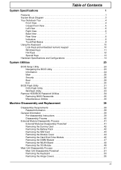
... Utilities 34 Removing BIOS Passwords 35 Miscellaneous Utilities 36 Machine Disassembly and Replacement 39 Disassembly Requirements 39 Related Information 39 General Information 39 Pre-disassembly Instructions 39 Disassembly Process 40 External Module Disassembly Process 41 External Modules Disassembly Flowchart 41 Removing the Dummy Card 42 Removing the Battery ...45 Removing the DIMM Module 47 Removing the WLAN Board 48 Removing the 3G Module 49 Main Unit Disassembly Process 51 Main Unit Disassembly Flowchart 51 Removing the Keyboard 53 Removing the Hinge Covers 55 vii
... Utilities 34 Removing BIOS Passwords 35 Miscellaneous Utilities 36 Machine Disassembly and Replacement 39 Disassembly Requirements 39 Related Information 39 General Information 39 Pre-disassembly Instructions 39 Disassembly Process 40 External Module Disassembly Process 41 External Modules Disassembly Flowchart 41 Removing the Dummy Card 42 Removing the Battery ...45 Removing the DIMM Module 47 Removing the WLAN Board 48 Removing the 3G Module 49 Main Unit Disassembly Process 51 Main Unit Disassembly Flowchart 51 Removing the Keyboard 53 Removing the Hinge Covers 55 vii
Aspire 1420P and 1820PT Service Guide
Page 8
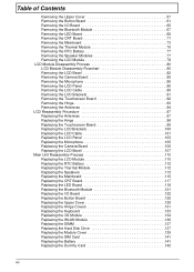
... 73 Removing the Thermal Module 76 Removing the RTC Battery 77 Removing the Speaker Modules 77 Removing the LCD Module 78 LCD Module Disassembly Process 80 LCD Module Disassembly Flowchart 80 Removing the LCD Bezel 82 Removing the Camera Board 85 Removing the Microphone 86 Removing the LCD Panel 86 Removing the...
... 73 Removing the Thermal Module 76 Removing the RTC Battery 77 Removing the Speaker Modules 77 Removing the LCD Module 78 LCD Module Disassembly Process 80 LCD Module Disassembly Flowchart 80 Removing the LCD Bezel 82 Removing the Camera Board 85 Removing the Microphone 86 Removing the LCD Panel 86 Removing the...

Aspire 1420P and 1820PT Service Guide
Page 49
...the removal and replacement of components, ensure all available cable channels and clips are replaced in the same position. Chapter 3 Machine Disassembly and Replacement This chapter contains step-by-step procedures on a flat, stable surface. Unplug the AC adapter and all peripherals....represent the actual model. IMPORTANT: Cable paths and positioning may not represent the final product color or configuration. Disassembly Requirements To disassemble the computer, you do the following tools: • Wrist grounding strap and conductive mat for preventing electrostatic ...
...the removal and replacement of components, ensure all available cable channels and clips are replaced in the same position. Chapter 3 Machine Disassembly and Replacement This chapter contains step-by-step procedures on a flat, stable surface. Unplug the AC adapter and all peripherals....represent the actual model. IMPORTANT: Cable paths and positioning may not represent the final product color or configuration. Disassembly Requirements To disassemble the computer, you do the following tools: • Wrist grounding strap and conductive mat for preventing electrostatic ...
Aspire 1420P and 1820PT Service Guide
Page 50
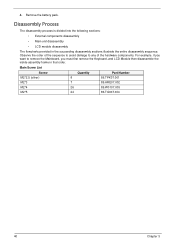
...components. For example, if you must first remove the Keyboard, and LCD Module then disassemble the inside assembly frame in the succeeding disassembly sections illustrate the entire disassembly sequence. 4. Main Screw List Screw Quantity Part Number M2*2.5 (silver) 8 86....86.W0107.003 M2*5 24 86.TG607.004 40 Chapter 3 Remove the battery pack. Disassembly Process The disassembly process is divided into the following sections: • External components disassembly • Main unit disassembly • LCD module disassembly The flowcharts provided in that order.
...components. For example, if you must first remove the Keyboard, and LCD Module then disassemble the inside assembly frame in the succeeding disassembly sections illustrate the entire disassembly sequence. 4. Main Screw List Screw Quantity Part Number M2*2.5 (silver) 8 86....86.W0107.003 M2*5 24 86.TG607.004 40 Chapter 3 Remove the battery pack. Disassembly Process The disassembly process is divided into the following sections: • External components disassembly • Main unit disassembly • LCD module disassembly The flowcharts provided in that order.
Aspire 1420P and 1820PT Service Guide
Page 51
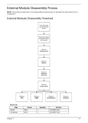
External Module Disassembly Process NOTE: The product previews seen in the disassembly procedures may not represent the final product color or configuration. External Modules Disassembly Flowchart Turn off system and peripherals power Disconnect power and signal cables from system Remove Dummy Card Remove Battery Remove SIM Card (Optional) Remove Lower Cover Remove HDD Remove DIMM Remove WLAN Board Remove 3G Board Screw List Step WLAN 3G Module Screw M2*3 M2*3 Quantity 1 1 Part No. 86.ARE07.002 86.ARE07.002 Chapter 3 41
External Module Disassembly Process NOTE: The product previews seen in the disassembly procedures may not represent the final product color or configuration. External Modules Disassembly Flowchart Turn off system and peripherals power Disconnect power and signal cables from system Remove Dummy Card Remove Battery Remove SIM Card (Optional) Remove Lower Cover Remove HDD Remove DIMM Remove WLAN Board Remove 3G Board Screw List Step WLAN 3G Module Screw M2*3 M2*3 Quantity 1 1 Part No. 86.ARE07.002 86.ARE07.002 Chapter 3 41
Aspire 1420P and 1820PT Service Guide
Page 61
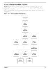
...cable channels and clips are used and that the cables are replaced in the disassembly procedures may not represent the actual model. NOTE: The product previews seen in the same position. Main Unit Disassembly Flowchart Remove External Modules before proceeding Remove Keyboard Remove Hinge Covers Remove Upper Cover... Remove Bluetooth Module Remove Thermal Module Remove Mainboard Remove RTC Battery Remove Speaker Module Remove LCD Module Chapter 3 51 Main Unit Disassembly Process IMPORTANT: Cable paths and positioning may not represent the final product color or configuration.
...cable channels and clips are used and that the cables are replaced in the disassembly procedures may not represent the actual model. NOTE: The product previews seen in the same position. Main Unit Disassembly Flowchart Remove External Modules before proceeding Remove Keyboard Remove Hinge Covers Remove Upper Cover... Remove Bluetooth Module Remove Thermal Module Remove Mainboard Remove RTC Battery Remove Speaker Module Remove LCD Module Chapter 3 51 Main Unit Disassembly Process IMPORTANT: Cable paths and positioning may not represent the final product color or configuration.

Aspire 1420P and 1820PT Service Guide
Page 90
...of components, ensure all available cable channels and clips are used and that the cables are replaced in the disassembly procedures may not represent the actual model. LCD Module Disassembly Flowchart Remove LCD Module from Main Unit before proceeding Remove LCD Module Bezel Remove Microphone Remove Camera Module Remove ...LCD Panel Remove LCD FPC Cable Remove Touchscreen Board Remove LCD Brackets Remove Hinges Remove Antennas 80 Chapter 3 LCD Module Disassembly Process IMPORTANT: Cable paths and positioning may not represent the final product color or configuration.
...of components, ensure all available cable channels and clips are used and that the cables are replaced in the disassembly procedures may not represent the actual model. LCD Module Disassembly Flowchart Remove LCD Module from Main Unit before proceeding Remove LCD Module Bezel Remove Microphone Remove Camera Module Remove ...LCD Panel Remove LCD FPC Cable Remove Touchscreen Board Remove LCD Brackets Remove Hinges Remove Antennas 80 Chapter 3 LCD Module Disassembly Process IMPORTANT: Cable paths and positioning may not represent the final product color or configuration.
Aspire 1420P and 1820PT Service Guide
Page 156
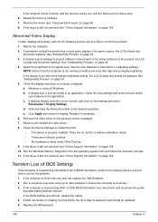
...Replace the Motherboard. 146 Chapter 4 Reseat the memory modules. 7. Remove the drives (see "Online Support Information" on page 165. See "Disassembly Process" on the desktop and select Personalize´ Display Settings. Adjust the brightness to the previous version if updated. 7. c. d. Readjust...Run a complete virus scan using up-to-date software to the desired resolution. If the computer is correctly configured: a. See "Disassembly Process" on adjusting settings. See the User Manual for instructions on page 34. 4. Check the Device Manager to correct the problem....
...Replace the Motherboard. 146 Chapter 4 Reseat the memory modules. 7. Remove the drives (see "Online Support Information" on page 165. See "Disassembly Process" on the desktop and select Personalize´ Display Settings. Adjust the brightness to the previous version if updated. 7. c. d. Readjust...Run a complete virus scan using up-to-date software to the desired resolution. If the computer is correctly configured: a. See "Disassembly Process" on adjusting settings. See the User Manual for instructions on page 34. 4. Check the Device Manager to correct the problem....

Aspire 1420P and 1820PT Service Guide
Page 162
.... e. Select the appropriate operating system, and click Next. h. Run Windows Check Disk by entering chkdsk /r from the list and click Next. Replace the HDD. See "Disassembly Process" on the Boot menu. 6. HDD Not Operating Correctly If the HDD does not operate correctly, perform the following actions one at a time to complete...
.... e. Select the appropriate operating system, and click Next. h. Run Windows Check Disk by entering chkdsk /r from the list and click Next. Replace the HDD. See "Disassembly Process" on the Boot menu. 6. HDD Not Operating Correctly If the HDD does not operate correctly, perform the following actions one at a time to complete...

Aspire 1420P and 1820PT Service Guide
Page 177
..." on the main board clears the CMOS of all user settings. 1. The Hardware Open Gap on page 73. 3. See "Removing the Mainboard" on page 69. 2. Disassemble the notebook and take out the Mainboard. Remove the RTC battery. Chapter 5 167 Turn the mainboard over, lift up the DIMM protective cover, and short...
..." on the main board clears the CMOS of all user settings. 1. The Hardware Open Gap on page 73. 3. See "Removing the Mainboard" on page 69. 2. Disassemble the notebook and take out the Mainboard. Remove the RTC battery. Chapter 5 167 Turn the mainboard over, lift up the DIMM protective cover, and short...
Aspire 1420P and 1820PT Service Guide
Page 211
... caps lock on indicator 8 Common Problems 144 CRT Cable Removing 115 D DIMM Module Removing 47 Display 3 display hotkeys 12 E Euro Key 13 Index External Module Disassembly Flowchart 41 F Features 1 FLASH Utility 31 Flash Utility 31 FRU (Field Replaceable Unit) List 169 H Hard Disk Drive Module Removing 45 Hibernation mode hotkey 12... 148 L LCD Bezel Removing 82, 107 LCD Brackets Removing 88, 101 LCD Cable Removing 88, 101 LCD Failure 147 LCD Module Removing 110 LCD Module Disassembly Flowchart 80 201
... caps lock on indicator 8 Common Problems 144 CRT Cable Removing 115 D DIMM Module Removing 47 Display 3 display hotkeys 12 E Euro Key 13 Index External Module Disassembly Flowchart 41 F Features 1 FLASH Utility 31 Flash Utility 31 FRU (Field Replaceable Unit) List 169 H Hard Disk Drive Module Removing 45 Hibernation mode hotkey 12... 148 L LCD Bezel Removing 82, 107 LCD Brackets Removing 88, 101 LCD Cable Removing 88, 101 LCD Failure 147 LCD Module Removing 110 LCD Module Disassembly Flowchart 80 201
Aspire 1420P and 1820PT Service Guide
Page 212
LCD Panel Removing 86, 103 M Main Unit Disassembly Flowchart 51 Mainboard Removing 115 media access on indicator 8 Memory Check 144 Microphone Removing 86, 103 Model Definition 177 N No Display Issue 145 num lock ...
LCD Panel Removing 86, 103 M Main Unit Disassembly Flowchart 51 Mainboard Removing 115 media access on indicator 8 Memory Check 144 Microphone Removing 86, 103 Model Definition 177 N No Display Issue 145 num lock ...


