Acer Aspire 1640Z and 1650Z Service Guide
Page 10
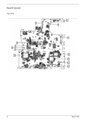
Board Layout Top View 4 Aspire 1640
Board Layout Top View 4 Aspire 1640
Acer Aspire 1640Z and 1650Z Service Guide
Page 11
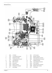
Bottom View 1 SW1 Lid Switch 3 CN2 Launch Board Connector 5 CN7 Keyboard Connector 7 CN5 Touchpad Board Connector 9 U17 Clock Generator 11 CN9 MDC Connector 13 CN13 Power Jack 15 CN14 Battery Connector 17 CN17 RJ45 & RJ11 Connector 19 U11 North Bridge Chapter 1 2 CN1 LCD Connector 4 CN3 Modem Connector 6 CN4 Bluetooth Module Connector 8 CN6 Internal Microphone Connector 10 U4 PCMCIA Connector 12 CN11 Internal Speaker Connector 14 CN12 CRT Connector 16 CN15 Optical Disk Drive Connector 18 CN26 Wireless LAN Controller 20 U13 CPU Socket 5
Bottom View 1 SW1 Lid Switch 3 CN2 Launch Board Connector 5 CN7 Keyboard Connector 7 CN5 Touchpad Board Connector 9 U17 Clock Generator 11 CN9 MDC Connector 13 CN13 Power Jack 15 CN14 Battery Connector 17 CN17 RJ45 & RJ11 Connector 19 U11 North Bridge Chapter 1 2 CN1 LCD Connector 4 CN3 Modem Connector 6 CN4 Bluetooth Module Connector 8 CN6 Internal Microphone Connector 10 U4 PCMCIA Connector 12 CN11 Internal Speaker Connector 14 CN12 CRT Connector 16 CN15 Optical Disk Drive Connector 18 CN26 Wireless LAN Controller 20 U13 CPU Socket 5
Acer Aspire 1640Z and 1650Z Service Guide
Page 25
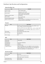
....0, Simple Boot Flag 1.0 Specification Built-in Intel® 915GM KBC NS97551 Intel (The controller is on the Wireless LAN card. Hardware Specifications and Configurations System Board Major Chip Item System core logic Memory controller Audio controller PCMCIA controller for socket Video controller Power and Keyboard controller Wireless controller (mini PCI) Processor...
....0, Simple Boot Flag 1.0 Specification Built-in Intel® 915GM KBC NS97551 Intel (The controller is on the Wireless LAN card. Hardware Specifications and Configurations System Board Major Chip Item System core logic Memory controller Audio controller PCMCIA controller for socket Video controller Power and Keyboard controller Wireless controller (mini PCI) Processor...
Acer Aspire 1640Z and 1650Z Service Guide
Page 52
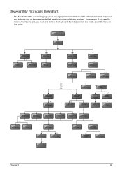
... HDD Bracket *1 ODD Support Bracket *1 CPU Heatsink Plate *3 VGA Heatsink Plate Touchpad Button Pad *2 ODD Bracket ODD *4 Main Board Touchpad Touchpad Scroll Key *2 DC Board *2 Speaker Set *4 PCMCIA Slot Touchpad Cable Upper Case Chapter 3 48 For example, if you must first remove the keyboard,... then disassemble the inside assembly frame in that need to remove the main board, you want to be removed during servicing. Disassembly Procedure Flowchart The flowchart on the succeeding page gives you a graphic representation on...
... HDD Bracket *1 ODD Support Bracket *1 CPU Heatsink Plate *3 VGA Heatsink Plate Touchpad Button Pad *2 ODD Bracket ODD *4 Main Board Touchpad Touchpad Scroll Key *2 DC Board *2 Speaker Set *4 PCMCIA Slot Touchpad Cable Upper Case Chapter 3 48 For example, if you must first remove the keyboard,... then disassemble the inside assembly frame in that need to remove the main board, you want to be removed during servicing. Disassembly Procedure Flowchart The flowchart on the succeeding page gives you a graphic representation on...
Acer Aspire 1640Z and 1650Z Service Guide
Page 60
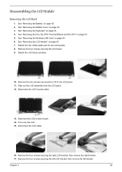
See "Removing the LCD Module" on page 50. 2. Remove the four screws securing the LCD bezel. 9. Discnnect the LCD inverter board. 14. Remove the four screws securing the left LCD bracket, then remove the left bracket. Remove the four screws securing the right LCD bracket, then ...
See "Removing the LCD Module" on page 50. 2. Remove the four screws securing the LCD bezel. 9. Discnnect the LCD inverter board. 14. Remove the four screws securing the left LCD bracket, then remove the left bracket. Remove the four screws securing the right LCD bracket, then ...
Acer Aspire 1640Z and 1650Z Service Guide
Page 62
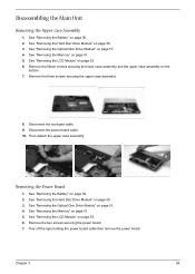
See "Removing the Optical Disc Drive Module" on page 53. 6. See "Removing the LCD Module" on page 51. 4. Disconnect the power board cable. 10. See "Removing the Battery" on page 51. 4. See "Removing the Optical Disc Drive Module" on page 50. 2. Chapter 3 58 See "...Removing the Memory" on page 50. 3. Disconnect the touchpad cable. 9. Remove the two screws securing the power board. 7. See "Removing the Hard Disc Drive Module" on page 51. 5. See "Removing the Hard Disc Drive Module" on page 53. 6. Disassembling the Main Unit...
See "Removing the Optical Disc Drive Module" on page 53. 6. See "Removing the LCD Module" on page 51. 4. Disconnect the power board cable. 10. See "Removing the Battery" on page 51. 4. See "Removing the Optical Disc Drive Module" on page 50. 2. Chapter 3 58 See "...Removing the Memory" on page 50. 3. Disconnect the touchpad cable. 9. Remove the two screws securing the power board. 7. See "Removing the Hard Disc Drive Module" on page 51. 5. See "Removing the Hard Disc Drive Module" on page 53. 6. Disassembling the Main Unit...
Acer Aspire 1640Z and 1650Z Service Guide
Page 63
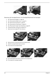
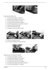
See "Removing the Power Board" on page 50. 2. Then remove the touchpad bracket. 11. See "Removing the Battery" on page 58. 5. See "Removing the Upper Case Assembly" on page 53. 3. ... bracket. 9. Pull back the tape covering the touchpad FFC. 7. See "Removing the Keyboard" on page 53. 4. Use a flat headed screw driver to detach the touchpad board. 12. Removing the Touchpad Bracket, the Touchpad...
See "Removing the Power Board" on page 50. 2. Then remove the touchpad bracket. 11. See "Removing the Battery" on page 58. 5. See "Removing the Upper Case Assembly" on page 53. 3. ... bracket. 9. Pull back the tape covering the touchpad FFC. 7. See "Removing the Keyboard" on page 53. 4. Use a flat headed screw driver to detach the touchpad board. 12. Removing the Touchpad Bracket, the Touchpad...
Acer Aspire 1640Z and 1650Z Service Guide
Page 64
..." on page 53. 4. Disconnect the SW DJ board cable. 7. See "Removing the Keyboard" on page 53. 4. See "Removing the Power Board" on page 58. 6. See "Removing the Upper Case Assembly" on page 58. 5. Then disconnect the audio board FFC cable. 9. Disconnect the speaker set from the... See "Removing the Middle Cover" on page 58. 6. Chapter 3 60 Disconnect the CIR receiver cable. 8. Removing the SW DJ Board Assembly 1. See "Removing the Power Board" on page 60. See "Removing the Speaker Set" on page 58. 5. Then detach the speaker set cable. 10. Removing the...
..." on page 53. 4. Disconnect the SW DJ board cable. 7. See "Removing the Keyboard" on page 53. 4. See "Removing the Power Board" on page 58. 6. See "Removing the Upper Case Assembly" on page 58. 5. Then disconnect the audio board FFC cable. 9. Disconnect the speaker set from the... See "Removing the Middle Cover" on page 58. 6. Chapter 3 60 Disconnect the CIR receiver cable. 8. Removing the SW DJ Board Assembly 1. See "Removing the Power Board" on page 60. See "Removing the Speaker Set" on page 58. 5. Then detach the speaker set cable. 10. Removing the...
Acer Aspire 1640Z and 1650Z Service Guide
Page 65
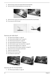
...the Middle Cover" on page 58. 5. See "Removing the Power Board" on page 53. 3. Remove the screw securing the audio board. 9. Remove the two screws securing the SW DJ board assembly. 8. See "Removing the Keyboard" on page 50. 2. Remove the SW DJ board assembly from the lower case. 9. See "Removing the Battery" ...on page 53. 4. Removing the VGA Thermal Module 1. See "Removing the Battery" on page 58. 6. Remove the two screws securing the SW DJ board and SW DJ board bracket. 10. See "Removing the Upper Case Assembly" on page 50. 61 Chapter 3 See "Removing the SW DJ...
...the Middle Cover" on page 58. 5. See "Removing the Power Board" on page 53. 3. Remove the screw securing the audio board. 9. Remove the two screws securing the SW DJ board assembly. 8. See "Removing the Keyboard" on page 50. 2. Remove the SW DJ board assembly from the lower case. 9. See "Removing the Battery" ...on page 53. 4. Removing the VGA Thermal Module 1. See "Removing the Battery" on page 58. 6. Remove the two screws securing the SW DJ board and SW DJ board bracket. 10. See "Removing the Upper Case Assembly" on page 50. 61 Chapter 3 See "Removing the SW DJ...
Acer Aspire 1640Z and 1650Z Service Guide
Page 66
..." on page 60. 8. See "Removing the Middle Cover" on page 53. 4. See "Removing the Keyboard" on page 53. 3. See "Removing the Power Board" on page 53. 3. Remove the three screws securing the VGA thermal module. 7. See "Removing the Middle Cover" on page 58. 5. See "Removing the Power... Board" on page 50. 2. See "Removing the Battery" on page 58. 5. See "Removing the Middle Cover" on page 58. 6. See "Removing the Upper ...
..." on page 60. 8. See "Removing the Middle Cover" on page 53. 4. See "Removing the Keyboard" on page 53. 3. See "Removing the Power Board" on page 53. 3. Remove the three screws securing the VGA thermal module. 7. See "Removing the Middle Cover" on page 58. 5. See "Removing the Power... Board" on page 50. 2. See "Removing the Battery" on page 58. 5. See "Removing the Middle Cover" on page 58. 6. See "Removing the Upper ...
Acer Aspire 1640Z and 1650Z Service Guide
Page 67
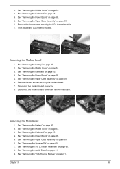
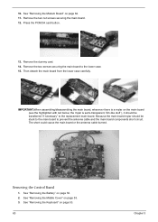
...prevent the antenna cable and the main board components short circuit. The short could cause the main board or the antenna cable burned. See "Removing the Middle Cover" on the main board (see the highlighted with red below; Then detach the main board from the lower case carefully. the ... Keyboard" on page 50. 2. Remove the two nut screws securing the main board. 12. Because the main board mylar should be stuck to the main board to the replacement main board. Removing the Control Board 1. See "Removing the Modem Board" on page 62. 11. Remove the two screws securing the main...
...prevent the antenna cable and the main board components short circuit. The short could cause the main board or the antenna cable burned. See "Removing the Middle Cover" on the main board (see the highlighted with red below; Then detach the main board from the lower case carefully. the ... Keyboard" on page 50. 2. Remove the two nut screws securing the main board. 12. Because the main board mylar should be stuck to the main board to the replacement main board. Removing the Control Board 1. See "Removing the Modem Board" on page 62. 11. Remove the two screws securing the main...
Acer Aspire 1640Z and 1650Z Service Guide
Page 68
Pop out the control board then remove it. See "Removing the Main Board" on page 60. 7. Turn over the main board as shown. 13. See "Removing the Speaker Set" on page 62. 12. See "Removing the VGA Thermal Module" on page 62. 11. See "Removing the Modem Board" on page 61. 10. See "Removing the SW DJ Board Assembly" on page 58. 6. See "Removing the Upper Case Assembly" on page 60. 8. See "Removing the Audio Board" on page 58. 5. Disconnect the control board antenna. 14. See "Removing the Power Board" on page 61. 9. Chapter 3 64 4.
Pop out the control board then remove it. See "Removing the Main Board" on page 60. 7. Turn over the main board as shown. 13. See "Removing the Speaker Set" on page 62. 12. See "Removing the VGA Thermal Module" on page 62. 11. See "Removing the Modem Board" on page 61. 10. See "Removing the SW DJ Board Assembly" on page 58. 6. See "Removing the Upper Case Assembly" on page 60. 8. See "Removing the Audio Board" on page 58. 5. Disconnect the control board antenna. 14. See "Removing the Power Board" on page 61. 9. Chapter 3 64 4.
Acer Aspire 1640Z and 1650Z Service Guide
Page 71
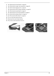
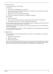
... module. 3. Boot from the diagnostics diskette and start the diagnostics program. 2. If an error occurs, reconnect the connector on the system board. Keyboard or Auxiliary Input Device Check Remove the external keyboard if the internal keyboard is passed as the program runs to FDD Test. 3.... does not work or an unexpected character appears, make sure that the flexible cable extending from the keyboard is required. Replace the main board. External CD-ROM Drive Check Do the following one label attached to it . Replace the keyboard. 3. System Check Procedures External Diskette ...
... module. 3. Boot from the diagnostics diskette and start the diagnostics program. 2. If an error occurs, reconnect the connector on the system board. Keyboard or Auxiliary Input Device Check Remove the external keyboard if the internal keyboard is passed as the program runs to FDD Test. 3.... does not work or an unexpected character appears, make sure that the flexible cable extending from the keyboard is required. Replace the main board. External CD-ROM Drive Check Do the following one label attached to it . Replace the keyboard. 3. System Check Procedures External Diskette ...
Acer Aspire 1640Z and 1650Z Service Guide
Page 72
... that the DIMM is fully installed into the connector. Follow the instructions in the test items. 4. Press F2 in the message window. Go to main board. 2. Disconnect the power adapter and install the charged battery pack; Power System Check To verify the symptom of these devices do not work, reconnect the...
... that the DIMM is fully installed into the connector. Follow the instructions in the test items. 4. Press F2 in the message window. Go to main board. 2. Disconnect the power adapter and install the charged battery pack; Power System Check To verify the symptom of these devices do not work, reconnect the...
Acer Aspire 1640Z and 1650Z Service Guide
Page 73
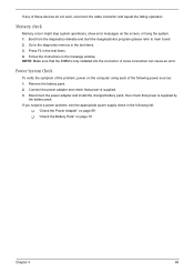
... +20.5V Pin 2: 0V, Ground 1. T If the voltage is not corrected, see "Check the Battery Pack" on page 83. See the following : T Replace the System board. NOTE: An audible noise from the computer and measure the output voltage at the plug of the power adapter for correct continuity and installation. 4. If...
... +20.5V Pin 2: 0V, Ground 1. T If the voltage is not corrected, see "Check the Battery Pack" on page 83. See the following : T Replace the System board. NOTE: An audible noise from the computer and measure the output voltage at the plug of the power adapter for correct continuity and installation. 4. If...
Acer Aspire 1640Z and 1650Z Service Guide
Page 74
... period of the total power remaining when installed in control Panel 2. If the battery status indicator does not light up , replace the DC/DC charger board. If the charge indicator still does not light up, replace the battery pack. Do not replace a non-defective FRU: 1. After you identify first the problem... to the touchpad pointer. Check the Battery Pack To check the battery pack, do the following : From Software: 1. Power off the computer. 2. Replace the system board.
... period of the total power remaining when installed in control Panel 2. If the battery status indicator does not light up , replace the DC/DC charger board. If the charge indicator still does not light up, replace the battery pack. Do not replace a non-defective FRU: 1. After you identify first the problem... to the touchpad pointer. Check the Battery Pack To check the battery pack, do the following : From Software: 1. Power off the computer. 2. Replace the system board.
Acer Aspire 1640Z and 1650Z Service Guide
Page 76
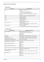
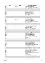
...W:xxxxh) Real Time Clock Error CMOS Battery Bad CMOS Checksum Error System disabled. System CMOS checksum bad - Hard disk drive System board Stuck Key see "Keyboard or Auxiliary Input Device Check" on page 67. Keyboard Controller Failed see "Keyboard or Auxiliary Input Device ...LOW In this situation BIOS will be shown before "Equipment Configuration Error") Memory Error at offset: nnnn DIMM System board System battery is specified. System board Chapter 4 72 CPU BIOS Update Code Mismatch 2. Default configuration used RTC battery Run BIOS Setup Utility to reconfigure...
...W:xxxxh) Real Time Clock Error CMOS Battery Bad CMOS Checksum Error System disabled. System CMOS checksum bad - Hard disk drive System board Stuck Key see "Keyboard or Auxiliary Input Device Check" on page 67. Keyboard Controller Failed see "Keyboard or Auxiliary Input Device ...LOW In this situation BIOS will be shown before "Equipment Configuration Error") Memory Error at offset: nnnn DIMM System board System battery is specified. System board Chapter 4 72 CPU BIOS Update Code Mismatch 2. Default configuration used RTC battery Run BIOS Setup Utility to reconfigure...
Acer Aspire 1640Z and 1650Z Service Guide
Page 77
... clock error RTC battery Run BIOS Setup Utility to reconfigure system time, then reboot system. Incorrect Drive A type - RTC battery System board Operating system not found by POST differed from CMOS Run "Load Default Settings" in BIOS Setup Utility System cache error - Diskette drive ... A: are properly identified. run SETUP Check the drive is defined with the proper diskette type in BIOS Setup Utility. RTC battery System board Allocation Error for device Run "Load Default Settings" in BIOS Setup Utility. Default configuration used Run "Load Default Settings" in BIOS Setup...
... clock error RTC battery Run BIOS Setup Utility to reconfigure system time, then reboot system. Incorrect Drive A type - RTC battery System board Operating system not found by POST differed from CMOS Run "Load Default Settings" in BIOS Setup Utility System cache error - Diskette drive ... A: are properly identified. run SETUP Check the drive is defined with the proper diskette type in BIOS Setup Utility. RTC battery System board Allocation Error for device Run "Load Default Settings" in BIOS Setup Utility. Default configuration used Run "Load Default Settings" in BIOS Setup...
Acer Aspire 1640Z and 1650Z Service Guide
Page 78
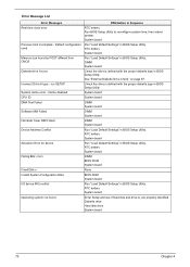
Error Message List No beep Error Messages FRU/Action in Sequence No beep, power-on indicator turns off and LCD is blank. LED board. No beep, power-on indicator turns on page 68. Power source (battery pack and power adapter). Ensure every connector is connected tightly and correctly. But ... See "Power System Check" on and LCD is blank. Reconnect the LCD connector Hard disk drive LCD inverter ID LCD cable LCD Inverter LCD System board No beep, power-on indicator turns on page 68. Reconnect the DIMM. See "Power System Check" on and LCD is blank. Speaker System...
Error Message List No beep Error Messages FRU/Action in Sequence No beep, power-on indicator turns off and LCD is blank. LED board. No beep, power-on indicator turns on page 68. Power source (battery pack and power adapter). Ensure every connector is connected tightly and correctly. But ... See "Power System Check" on and LCD is blank. Reconnect the LCD connector Hard disk drive LCD inverter ID LCD cable LCD Inverter LCD System board No beep, power-on indicator turns on page 68. Reconnect the DIMM. See "Power System Check" on and LCD is blank. Speaker System...
Acer Aspire 1640Z and 1650Z Service Guide
Page 80
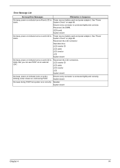
... devices Initialize all video adapters in system QuietBoot start (optional) Shadow video BIOS ROM Display BIOS copyright notice Display CPU type and speed Initialize EISA board Test keyboard Set key click if enabled Test for unexpected interrupts Initialize POST display service Display prompt "Press F2 to enter SETUP" Disable CPU cache...
... devices Initialize all video adapters in system QuietBoot start (optional) Shadow video BIOS ROM Display BIOS copyright notice Display CPU type and speed Initialize EISA board Test keyboard Set key click if enabled Test for unexpected interrupts Initialize POST display service Display prompt "Press F2 to enter SETUP" Disable CPU cache...


