
Aspire 1500 Service Guide
Page 7
... 44 Removing the Battery 46 Removing the Memory Module 47 Removing the Modem Board 48 Removing the Hard Disk Drive Module 49 Removing the LCD Module 50 Disassembling the LCD Module 53 Disassembling the Main Unit 57 System Upgrade Procedure 67 Assembling the Main Unit 68 Assembling the... LCD Module 77 Installing the LCD Module 81 Installing the Hard Disk Drive Module 84 Installing the Modem Board 85 Installing the Memory Module 86 Installing the Battery 87 Chapter 4 ...
... 44 Removing the Battery 46 Removing the Memory Module 47 Removing the Modem Board 48 Removing the Hard Disk Drive Module 49 Removing the LCD Module 50 Disassembling the LCD Module 53 Disassembling the Main Unit 57 System Upgrade Procedure 67 Assembling the Main Unit 68 Assembling the... LCD Module 77 Installing the LCD Module 81 Installing the Hard Disk Drive Module 84 Installing the Modem Board 85 Installing the Memory Module 86 Installing the Battery 87 Chapter 4 ...

Aspire 1500 Service Guide
Page 10
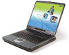
...Memory) support T High-capacity, Enhanced-IDE hard disk Display T T T T T T The 14.1" XGA (1024X768 resolution), or 15.0" SXGA+ (1400X1050 resolution) TFT LCD panel provides a large viewing area for maximum efficiency and ease-of-use 3D graphics support Support simultaneous display between... LCD and CRT display S-video for output to television or display device that supports S-video input "Automatic LCD dim" feature that automatically selects the best setting for the display in order to conserve...
...Memory) support T High-capacity, Enhanced-IDE hard disk Display T T T T T T The 14.1" XGA (1024X768 resolution), or 15.0" SXGA+ (1400X1050 resolution) TFT LCD panel provides a large viewing area for maximum efficiency and ease-of-use 3D graphics support Support simultaneous display between... LCD and CRT display S-video for output to television or display device that supports S-video input "Automatic LCD dim" feature that automatically selects the best setting for the display in order to conserve...
Aspire 1500 Service Guide
Page 13
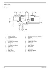
Board Layout Top View 1 Line-in/MIC Connector 2 Line-out/S/PDIF Connector 3 LAN Connector 4 USB Connector 5 LCD Inverter Cable Connector 6 CRT Connector 7 TV-out Connector 8 LCD Coaxial Cable Connector 9 Mini PCI Socket 10 VGA Chip 11 North Bridge 12 Printer Connector 13 AC Adapter Connector 14 Switch Cable Connector (LCD Lid Switch) 15 CPU Socket 16 RTC Battery Connector 17 Fan Cable Connector 18 Touchpad Cable Connector 19 HDD Connector 20 Keyboard Connector 21 Speaker Connector 22 ODD Connector 23 South Bridge 24 FDD Connector 25 Launch Cable Connector 26 PCMCIA Slot 4 Aspire 1500
Board Layout Top View 1 Line-in/MIC Connector 2 Line-out/S/PDIF Connector 3 LAN Connector 4 USB Connector 5 LCD Inverter Cable Connector 6 CRT Connector 7 TV-out Connector 8 LCD Coaxial Cable Connector 9 Mini PCI Socket 10 VGA Chip 11 North Bridge 12 Printer Connector 13 AC Adapter Connector 14 Switch Cable Connector (LCD Lid Switch) 15 CPU Socket 16 RTC Battery Connector 17 Fan Cable Connector 18 Touchpad Cable Connector 19 HDD Connector 20 Keyboard Connector 21 Speaker Connector 22 ODD Connector 23 South Bridge 24 FDD Connector 25 Launch Cable Connector 26 PCMCIA Slot 4 Aspire 1500
Aspire 1500 Service Guide
Page 15
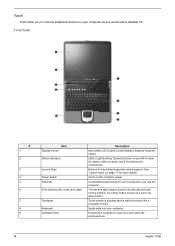
Turns on page 17 for your hands when you use . 6 Aspire 1500 Inputs data into your computer as a scroll up/ down button. Comfortable support area for more details. Enables the computer to show the status of the ... as you would with a desktop PC. Touch-sensitive pointing device which functions like the left , center and right) Touchpad Keyboard Ventilation Slot Description Also called LCD (Liquid Crystal Display), displays computer output. LEDs (Light Emitting Diodes) that turn on and off to stay cool, even after the prolonged use the computer...
Turns on page 17 for your hands when you use . 6 Aspire 1500 Inputs data into your computer as a scroll up/ down button. Comfortable support area for more details. Enables the computer to show the status of the ... as you would with a desktop PC. Touch-sensitive pointing device which functions like the left , center and right) Touchpad Keyboard Ventilation Slot Description Also called LCD (Liquid Crystal Display), displays computer output. LEDs (Light Emitting Diodes) that turn on and off to stay cool, even after the prolonged use the computer...

Aspire 1500 Service Guide
Page 18
... Universal Serial Bus devices(e.g., USB mouse, USB camera). Acceptis audio line-in devices (e.g., audio CD player, stereo walkman). Chapter 1 9 Connects to a display device (e.g., external monitor, LCD projector) and displays up to 16M colors at 1024x768 resolution Connects to a television or display device with S-video input. Network jack Connects to an Ethernet...
... Universal Serial Bus devices(e.g., USB mouse, USB camera). Acceptis audio line-in devices (e.g., audio CD player, stereo walkman). Chapter 1 9 Connects to a display device (e.g., external monitor, LCD projector) and displays up to 16M colors at 1024x768 resolution Connects to a television or display device with S-video input. Network jack Connects to an Ethernet...
Aspire 1500 Service Guide
Page 30
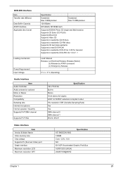
... channel 0 DMA channel 1 IRQ10, IRQ11 Video Interface Item Vendor & Model Name Video memory size Chip voltage Supports ZV (Zoomed Video) port Graph interface Maximum resolution LCD Maximum resolution CRT Specification ATI RADEON 9600 128MB Core / 2.5V, 1.5V, NO 8X AGP (Accelerated Graphic Port) Bus 1600X1200 (UXGA) 2048X1536@60HZ Chapter 1 21
... channel 0 DMA channel 1 IRQ10, IRQ11 Video Interface Item Vendor & Model Name Video memory size Chip voltage Supports ZV (Zoomed Video) port Graph interface Maximum resolution LCD Maximum resolution CRT Specification ATI RADEON 9600 128MB Core / 2.5V, 1.5V, NO 8X AGP (Accelerated Graphic Port) Bus 1600X1200 (UXGA) 2048X1536@60HZ Chapter 1 21
Aspire 1500 Service Guide
Page 32
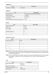
....4 Chapter 1 23 Avoid touching the DC-AC inverter area while the system unit is an EEPROM in the inverter, which stores its supported LCD type and ID code. NOTE: There is turned on. key Yes Yes Battery Item Vendor & model name Battery Type Pack capacity Cell voltage... Total number of battery cell Package configuration Package voltage SANYO Li-ION 6600mAH 3.8V / 1.2V 12 4529 / 8S 41.8V / 9.6V Specification DC-AC LCD Inverter Item Vendor & model name Input voltage (V) Input current (mA) Output voltage (Vrms, no load) Output voltage frequency (kHz) Output Current/Lamp Ambit ...
....4 Chapter 1 23 Avoid touching the DC-AC inverter area while the system unit is an EEPROM in the inverter, which stores its supported LCD type and ID code. NOTE: There is turned on. key Yes Yes Battery Item Vendor & model name Battery Type Pack capacity Cell voltage... Total number of battery cell Package configuration Package voltage SANYO Li-ION 6600mAH 3.8V / 1.2V 12 4529 / 8S 41.8V / 9.6V Specification DC-AC LCD Inverter Item Vendor & model name Input voltage (V) Input current (mA) Output voltage (Vrms, no load) Output voltage frequency (kHz) Output Current/Lamp Ambit ...
Aspire 1500 Service Guide
Page 33
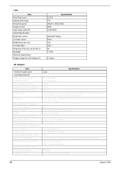
... an efficiency of 80% minimum, when measured at contact discharge) 3000Vac 0.25 mA max. (@ 254Vac, 60Hz) 24 Aspire 1500 LCD Item Pixel Pitch (mm) Display technology Resolution(pixel) Support colors View Angle (U/D/L/R) Optical Specification Brightness control Contrast control Brightness ...(cd/m sq.) Contrast Ratio Response Time (ms) (at 25 dec C) Backlight Electrical Specification Supply voltage for LCD display (V) Specification 0.2175 TFT SXGA+ (1400x1050) 262K 10/30/40/40 Keyboard hotkey None 150 250:1 50 1 CCFL 3.3 (typ.) ...
... an efficiency of 80% minimum, when measured at contact discharge) 3000Vac 0.25 mA max. (@ 254Vac, 60Hz) 24 Aspire 1500 LCD Item Pixel Pitch (mm) Display technology Resolution(pixel) Support colors View Angle (U/D/L/R) Optical Specification Brightness control Contrast control Brightness ...(cd/m sq.) Contrast Ratio Response Time (ms) (at 25 dec C) Backlight Electrical Specification Supply voltage for LCD display (V) Specification 0.2175 TFT SXGA+ (1400x1050) 262K 10/30/40/40 Keyboard hotkey None 150 250:1 50 1 CCFL 3.3 (typ.) ...
Aspire 1500 Service Guide
Page 35
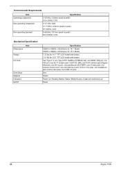
... Switch Specification 326(W) x 290(D) x 38.6(H)mm for 14.1" Model 326(W) x 290(D) x 42.9(H)mm for 15.0" Model 7.32 Ibs for 14.1" TFT LCD model with battery 7.51 Ibs for 15.0" TFT LCD model with battery Two Type II or one Type III PC CardBus (PCMCIA) slot, one IEEE 1394 port, one FIR port... mini jack), one headphone jack (3.5mm mini jack), four USB 2.0 ports One Plastic Power-on, Standby, Battery Status, Media Access, CapsLock and NumLock Power 26 Aspire 1500
... Switch Specification 326(W) x 290(D) x 38.6(H)mm for 14.1" Model 326(W) x 290(D) x 42.9(H)mm for 15.0" Model 7.32 Ibs for 14.1" TFT LCD model with battery 7.51 Ibs for 15.0" TFT LCD model with battery Two Type II or one Type III PC CardBus (PCMCIA) slot, one IEEE 1394 port, one FIR port... mini jack), one headphone jack (3.5mm mini jack), four USB 2.0 ports One Plastic Power-on, Standby, Battery Status, Media Access, CapsLock and NumLock Power 26 Aspire 1500
Aspire 1500 Service Guide
Page 40
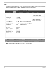
... differ. PhoenixBIOS Setup Utility Information Main Advanced Security Boot Exit System Time: System Date: System Memory: Extended Memory: VGA Memory: Quiet Boot: Power on display: LCD Auto Dim: Wakeup from LAN F12 Boot Menu Item Specific Help [18:48:04] [11/26/2003] , , or selects field. 640 KB Shows system memory...
... differ. PhoenixBIOS Setup Utility Information Main Advanced Security Boot Exit System Time: System Date: System Memory: Extended Memory: VGA Memory: Quiet Boot: Power on display: LCD Auto Dim: Wakeup from LAN F12 Boot Menu Item Specific Help [18:48:04] [11/26/2003] , , or selects field. 640 KB Shows system memory...
Aspire 1500 Service Guide
Page 41
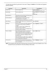
... This field reports the memory size of the system. This is because the user is fixed to 32MB Determines if Customer Logo will be in LCD only mode. Settings in these cases. Format MM/DD/YYYY (month/day/ year) System Date This field reports the memory size of the extended memory... in this screen. Memory size is not allowed to save power when AC is connected, the power on display LCD Auto Dim Description Format/Option Sets the system time. Disabled: Customer Logo is not displayed, and Summary Screen is disabled. If any display device is...
... This field reports the memory size of the system. This is because the user is fixed to 32MB Determines if Customer Logo will be in LCD only mode. Settings in these cases. Format MM/DD/YYYY (month/day/ year) System Date This field reports the memory size of the extended memory... in this screen. Memory size is not allowed to save power when AC is connected, the power on display LCD Auto Dim Description Format/Option Sets the system time. Disabled: Customer Logo is not displayed, and Summary Screen is disabled. If any display device is...
Aspire 1500 Service Guide
Page 53
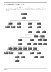
..., you on the components that order. Start Battery HDD Module *2 HDD HDD Holder *2 Dimm Cover Memory *1 Modem Cover *2 Modem Board Hinge Caps *2 Middle Cover Keyboard *6 LCD Module *2 Launch Board Lower Case Assembly *2 FDD Module *3 *3 *11 *4 RTC Battery *3 Mini PCI Card Plate Upper Case Assembly Disconnect Wireless LAN Antenna *4 Thermal Module *4 Wireless...
..., you on the components that order. Start Battery HDD Module *2 HDD HDD Holder *2 Dimm Cover Memory *1 Modem Cover *2 Modem Board Hinge Caps *2 Middle Cover Keyboard *6 LCD Module *2 Launch Board Lower Case Assembly *2 FDD Module *3 *3 *11 *4 RTC Battery *3 Mini PCI Card Plate Upper Case Assembly Disconnect Wireless LAN Antenna *4 Thermal Module *4 Wireless...

Aspire 1500 Service Guide
Page 54
LCD Module 4 LCD Cushions *4 LCD Bezel *1 Inverter *4 LCD LCD Panel LCD Coaxial Cable *4 LCD Brackets Screw List Item Description A SCRW MAC FLAT M2.5*L4 NI NYLOK B SCREW M2.0*L10 NYLOK C SCREW M2*3 NYLON 1JMCPC-420325 D SCREW M2.5X6 E SCREW M3x4(86.9A524.4R0) F SCREW M2X2.0 G SCREW WAFER NYLOK NI 2ML3 H SCRW M2*4 WAFER NI I SCRW M2.5*3 WAFER NI J SCREW M2.5*4L NI K SCW HEX NYL I#R-40/O#4-40 L5.5 45 Chapter 3
LCD Module 4 LCD Cushions *4 LCD Bezel *1 Inverter *4 LCD LCD Panel LCD Coaxial Cable *4 LCD Brackets Screw List Item Description A SCRW MAC FLAT M2.5*L4 NI NYLOK B SCREW M2.0*L10 NYLOK C SCREW M2*3 NYLON 1JMCPC-420325 D SCREW M2.5X6 E SCREW M3x4(86.9A524.4R0) F SCREW M2X2.0 G SCREW WAFER NYLOK NI 2ML3 H SCRW M2*4 WAFER NI I SCRW M2.5*3 WAFER NI J SCREW M2.5*4L NI K SCW HEX NYL I#R-40/O#4-40 L5.5 45 Chapter 3

Aspire 1500 Service Guide
Page 59
Removing the LCD Module Removing the Middle Cover 1. Remove the screw that secures the middle cover. 4. See "Removing the Battery" on the other side. 6. Disconnect the launch board cable then remove the middle cover off the main unit. . Removing the Launch Board 1. Remove the left hinge cap. 5. Detach the middle cover from the machine. 7. Chapter 3 50 Then remove the screw holding the middle cover on page 46.. 2. See "Removing the Battery" on page 46.. To remove the middle cover, first use a plastic flat screwdriver to remove the right hinge cap. 3.
Removing the LCD Module Removing the Middle Cover 1. Remove the screw that secures the middle cover. 4. See "Removing the Battery" on the other side. 6. Disconnect the launch board cable then remove the middle cover off the main unit. . Removing the Launch Board 1. Remove the left hinge cap. 5. Detach the middle cover from the machine. 7. Chapter 3 50 Then remove the screw holding the middle cover on page 46.. 2. See "Removing the Battery" on page 46.. To remove the middle cover, first use a plastic flat screwdriver to remove the right hinge cap. 3.

Aspire 1500 Service Guide
Page 60
... the Middle Cover" on the left. 6. two on the right and two on page 50.. 3. Then you can remove the entire LCD module from the middle cover. Then disconnect the LCD inverter cable. 5. two on the right and two on the bottom; Remove the two screws on the left . 7. one on the... right and the other on page 46.. 2. 2. See "Removing the Battery" on the left .Remove the four screws holding the LCD hinge; Remove the two screws and then detach the launch board from the main unit. 51 Chapter 3 Remove the four screws holding the...
... the Middle Cover" on the left. 6. two on the right and two on page 50.. 3. Then you can remove the entire LCD module from the middle cover. Then disconnect the LCD inverter cable. 5. two on the right and two on the bottom; Remove the two screws on the left . 7. one on the... right and the other on page 46.. 2. 2. See "Removing the Battery" on the left .Remove the four screws holding the LCD hinge; Remove the two screws and then detach the launch board from the main unit. 51 Chapter 3 Remove the four screws holding the...

Aspire 1500 Service Guide
Page 62
...page 53.. 6. To remove the inverter board, first remove one screw from the LCD module. See "Removing the Launch Board" on page 51.. 5. See "Removing the LCD Module" on page 50.. 4. See "Removing the LCD Module" on page 50.. 4. Use plastic tweezers to remove the four screw pads..., and then remove the four screws that fasten the LCD bezel. 6. Removing the Inverter Board (15" LCD) 1. Disassembling the LCD Module Removing the LCD Bezel 1. Snap off the bezel carefully, and then remove the LCD bezel from the inverter board. 7. See "Removing the Launch Board" on ...
...page 53.. 6. To remove the inverter board, first remove one screw from the LCD module. See "Removing the Launch Board" on page 51.. 5. See "Removing the LCD Module" on page 50.. 4. See "Removing the LCD Module" on page 50.. 4. Use plastic tweezers to remove the four screw pads..., and then remove the four screws that fasten the LCD bezel. 6. Removing the Inverter Board (15" LCD) 1. Disassembling the LCD Module Removing the LCD Bezel 1. Snap off the bezel carefully, and then remove the LCD bezel from the inverter board. 7. See "Removing the Launch Board" on ...

Aspire 1500 Service Guide
Page 63
..." on page 53. 6. see "Removing the LCD Bezel" on page 50.. 3. Then take the LCD out of the LCD panel. See "Removing the LCD Module" on page 46.. 2. See "Removing the Battery" on page 51.. 5. Removing the 15" TFT LCD 1. NOTE: Please arrange the LCD inverter cable well to the LCD panel as the picture below shows...
..." on page 53. 6. see "Removing the LCD Bezel" on page 50.. 3. Then take the LCD out of the LCD panel. See "Removing the LCD Module" on page 46.. 2. See "Removing the Battery" on page 51.. 5. Removing the 15" TFT LCD 1. NOTE: Please arrange the LCD inverter cable well to the LCD panel as the picture below shows...

Aspire 1500 Service Guide
Page 64
...page 50.. 3. See "Removing the 15" TFT LCD" on page 51.. 5. Then remove the left LCD bracket. See "Removing the LCD Module" on page 54.. 8. See "Removing the LCD Module" on page 50.. 4. Tear off the mylar fastening the LCD coaxial cable, then disconnect the coaxial cable. 55 ... on page 53.. 7. See "Removing the LCD Bezel" on page 46.. 2. See "Removing the Battery" on page 53.. 6. Removing the LCD Brackets 1. See "Removing the 15" TFT LCD" on page 53.. 6. See "Removing the LCD Bezel" on page 54.. 8. Removing the LCD Coaxial Cable 1. See "Removing the Battery"...
...page 50.. 3. See "Removing the 15" TFT LCD" on page 51.. 5. Then remove the left LCD bracket. See "Removing the LCD Module" on page 54.. 8. See "Removing the LCD Module" on page 50.. 4. Tear off the mylar fastening the LCD coaxial cable, then disconnect the coaxial cable. 55 ... on page 53.. 7. See "Removing the LCD Bezel" on page 46.. 2. See "Removing the Battery" on page 53.. 6. Removing the LCD Brackets 1. See "Removing the 15" TFT LCD" on page 53.. 6. See "Removing the LCD Bezel" on page 54.. 8. Removing the LCD Coaxial Cable 1. See "Removing the Battery"...

Aspire 1500 Service Guide
Page 65
Removing the LCD Hinges 1. Remove the screw holding the left hinge, then remove the left hinge. See "Removing the Battery" on page 53.. 6. See "Removing the LCD Bezel" on page 46.. 2. See "Removing the Launch Board" on page 53.. 7. See "Removing the Inverter Board (15" LCD)" on page 50.. 4. See "Removing the 15" TFT LCD" on page 50.. 3. See "Removing the Middle Cover" on page 54.. 8. Chapter 3 56 See "Removing the LCD Module" on page 51.. 5. Remove the screw holding the right hinge, then remove the right hinge. 9.
Removing the LCD Hinges 1. Remove the screw holding the left hinge, then remove the left hinge. See "Removing the Battery" on page 53.. 6. See "Removing the LCD Bezel" on page 46.. 2. See "Removing the Launch Board" on page 53.. 7. See "Removing the Inverter Board (15" LCD)" on page 50.. 4. See "Removing the 15" TFT LCD" on page 50.. 3. See "Removing the Middle Cover" on page 54.. 8. Chapter 3 56 See "Removing the LCD Module" on page 51.. 5. Remove the screw holding the right hinge, then remove the right hinge. 9.
Aspire 1500 Service Guide
Page 66
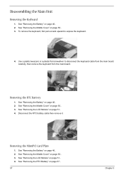
Removing the RTC Battery 1. See "Removing the LCD Module" on page 57.. 57 Chapter 3 Disconnect the RTC battery cable then remove it. Use a plastic tweezers or a plastic flat screwdriver to expose the keyboard. 4. ...See "Removing the RTC Battery" on page 51.. 4. Disassembling the Main Unit Removing the Keyboard 1. See "Removing the Battery" on page 51.. 4. See "Removing the LCD Module" on page 46.. 2. See "Removing the Battery" on page 50.. 3. To remove the keyboard, first pull out and upward to disconnect the keyboard cable...
Removing the RTC Battery 1. See "Removing the LCD Module" on page 57.. 57 Chapter 3 Disconnect the RTC battery cable then remove it. Use a plastic tweezers or a plastic flat screwdriver to expose the keyboard. 4. ...See "Removing the RTC Battery" on page 51.. 4. Disassembling the Main Unit Removing the Keyboard 1. See "Removing the Battery" on page 51.. 4. See "Removing the LCD Module" on page 46.. 2. See "Removing the Battery" on page 50.. 3. To remove the keyboard, first pull out and upward to disconnect the keyboard cable...


