
Aspire 1500 Service Guide
Page 7
... Diagram 3 Board Layout 4 Top View 4 Bottom View 5 Panel 6 Front Panel 6 Left Panel 7 Right Panel 8 Rear Panel 9 Bottom Panel 10 Indicators 11 Understanding the icons 12 Keyboard 13 Special keys 13 Hot Keys 15 Hardware Specifications and Configurations 18 Chapter 2 System Utilities 28 BIOS Setup Utility 28 Navigating the BIOS Utility 29...
... Diagram 3 Board Layout 4 Top View 4 Bottom View 5 Panel 6 Front Panel 6 Left Panel 7 Right Panel 8 Rear Panel 9 Bottom Panel 10 Indicators 11 Understanding the icons 12 Keyboard 13 Special keys 13 Hot Keys 15 Hardware Specifications and Configurations 18 Chapter 2 System Utilities 28 BIOS Setup Utility 28 Navigating the BIOS Utility 29...
Aspire 1500 Service Guide
Page 8
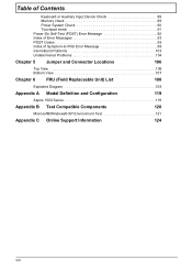
Table of Contents Keyboard or Auxiliary Input Device Check 89 Memory check 89 Power System Check 90 Touchpad check 91 Power-On Self-Test (POST) Error Message 92 Index ... Connector Locations 106 Top View 106 Bottom View 107 Chapter 6 FRU (Field Replaceable Unit) List 108 Exploded Diagram 109 Appendix A Model Definition and Configuration 119 Aspire 1500 Series 119 Appendix B Test Compatible Components 120 Microsoft®Windows® XP Environment Test 121 Appendix C Online Support Information 124 VIII
Table of Contents Keyboard or Auxiliary Input Device Check 89 Memory check 89 Power System Check 90 Touchpad check 91 Power-On Self-Test (POST) Error Message 92 Index ... Connector Locations 106 Top View 106 Bottom View 107 Chapter 6 FRU (Field Replaceable Unit) List 108 Exploded Diagram 109 Appendix A Model Definition and Configuration 119 Aspire 1500 Series 119 Appendix B Test Compatible Components 120 Microsoft®Windows® XP Environment Test 121 Appendix C Online Support Information 124 VIII

Aspire 1500 Service Guide
Page 10
... designed with the user in -one design (incorporating hard drive, optical drive and floppy disk drive) T Rugged, yet extremely protable, construction T Stylish appearance T Full-size keyboard with four programmable launch keys Chapter 1 1 Here are just a few of its many features: Performance T The AMD AthlonTM 64 processor 3000+~3400+ T AMD Hyper Transport...
... designed with the user in -one design (incorporating hard drive, optical drive and floppy disk drive) T Rugged, yet extremely protable, construction T Stylish appearance T Full-size keyboard with four programmable launch keys Chapter 1 1 Here are just a few of its many features: Performance T The AMD AthlonTM 64 processor 3000+~3400+ T AMD Hyper Transport...
Aspire 1500 Service Guide
Page 13
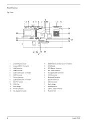
Board Layout Top View 1 Line-in/MIC Connector 2 Line-out/S/PDIF Connector 3 LAN Connector 4 USB Connector 5 LCD Inverter Cable Connector 6 CRT Connector 7 TV-out Connector 8 LCD Coaxial Cable Connector 9 Mini PCI Socket 10 VGA Chip 11 North Bridge 12 Printer Connector 13 AC Adapter Connector 14 Switch Cable Connector (LCD Lid Switch) 15 CPU Socket 16 RTC Battery Connector 17 Fan Cable Connector 18 Touchpad Cable Connector 19 HDD Connector 20 Keyboard Connector 21 Speaker Connector 22 ODD Connector 23 South Bridge 24 FDD Connector 25 Launch Cable Connector 26 PCMCIA Slot 4 Aspire 1500
Board Layout Top View 1 Line-in/MIC Connector 2 Line-out/S/PDIF Connector 3 LAN Connector 4 USB Connector 5 LCD Inverter Cable Connector 6 CRT Connector 7 TV-out Connector 8 LCD Coaxial Cable Connector 9 Mini PCI Socket 10 VGA Chip 11 North Bridge 12 Printer Connector 13 AC Adapter Connector 14 Switch Cable Connector (LCD Lid Switch) 15 CPU Socket 16 RTC Battery Connector 17 Fan Cable Connector 18 Touchpad Cable Connector 19 HDD Connector 20 Keyboard Connector 21 Speaker Connector 22 ODD Connector 23 South Bridge 24 FDD Connector 25 Launch Cable Connector 26 PCMCIA Slot 4 Aspire 1500
Aspire 1500 Service Guide
Page 15
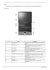
... Panel # 1 2 3 4 5 6 7 8 9 Item Display screen Status indicators Launch Keys Power switch Palmrest Click buttons (left and right mouse buttons, the center button serves as you use . 6 Aspire 1500 Touch-sensitive pointing device which functions like the left , center and right) Touchpad Keyboard Ventilation Slot Description Also called LCD (Liquid Crystal Display), displays computer output.
... Panel # 1 2 3 4 5 6 7 8 9 Item Display screen Status indicators Launch Keys Power switch Palmrest Click buttons (left and right mouse buttons, the center button serves as you use . 6 Aspire 1500 Touch-sensitive pointing device which functions like the left , center and right) Touchpad Keyboard Ventilation Slot Description Also called LCD (Liquid Crystal Display), displays computer output.

Aspire 1500 Service Guide
Page 22
... keys. A better solution would be to do a lot of the keycaps. Special keys Lock keys The keyboard has three lock keys which you can toggle on the keys. When [ is in uppercase. To simplify the keyboard legend, cursor-control key symbols are in numeric mode. The keys function as a calculator (complete with...
... keys. A better solution would be to do a lot of the keycaps. Special keys Lock keys The keyboard has three lock keys which you can toggle on the keys. When [ is in uppercase. To simplify the keyboard legend, cursor-control key symbols are in numeric mode. The keys function as a calculator (complete with...
Aspire 1500 Service Guide
Page 23
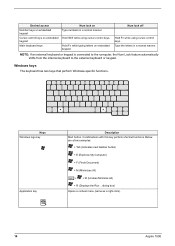
...Type numbers in a normal manner. NOTE: If an external keyboard or keypad is connected to the computer, the Num Lock feature automatically shifts from the internal keyboard to the external keyboard or keypad. Windows keys The keyboard has two keys that perform Windows-specific functions. Type the ... keypad Cursor-control keys on embedded keypad Main keyboard keys Num lock on embedded keypad. Num lock off Hold Fn while using cursor-control keys. dialog box) Opens a context menu (same as a right-click). 14 Aspire 1500 Combinations with this key perform shortcut functions. Keys...
...Type numbers in a normal manner. NOTE: If an external keyboard or keypad is connected to the computer, the Num Lock feature automatically shifts from the internal keyboard to the external keyboard or keypad. Windows keys The keyboard has two keys that perform Windows-specific functions. Type the ... keypad Cursor-control keys on embedded keypad Main keyboard keys Num lock on embedded keypad. Num lock off Hold Fn while using cursor-control keys. dialog box) Opens a context menu (same as a right-click). 14 Aspire 1500 Combinations with this key perform shortcut functions. Keys...
Aspire 1500 Service Guide
Page 25
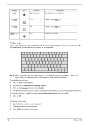
... on OK. Locate the Euro symbol on OK. 5. Hold aGr and press the Euro symbol. 16 Aspire 1500 Verify that the keyboard layout used for US keyboard users: The keyboard layout is set to United States-International. If not, select and click on ADD, then select United ...EN English (United States) is set to United States-International or United Kingdom or if you have a keyboard with a European layout, you first set to United States-international. Click on your keyboard layout is set up Windows. Double-click on Start, Control Panel. 2. Click on Regional and Language...
... on OK. Locate the Euro symbol on OK. 5. Hold aGr and press the Euro symbol. 16 Aspire 1500 Verify that the keyboard layout used for US keyboard users: The keyboard layout is set to United States-International. If not, select and click on ADD, then select United ...EN English (United States) is set to United States-International or United Kingdom or if you have a keyboard with a European layout, you first set to United States-international. Click on your keyboard layout is set up Windows. Double-click on Start, Control Panel. 2. Click on Regional and Language...

Aspire 1500 Service Guide
Page 26
Launch Keys Located at the top of (optional) wireless communication. They are users programmable. Opens (optional) wireless connectivity and indicates status of the keyboard are called launch keys. By default, P1 and P2 are designated as wireless LAN/Bluetooth, Web Browser button, mail button, P1 andP2. The LED of ...
Launch Keys Located at the top of (optional) wireless communication. They are users programmable. Opens (optional) wireless connectivity and indicates status of the keyboard are called launch keys. By default, P1 and P2 are designated as wireless LAN/Bluetooth, Web Browser button, mail button, P1 andP2. The LED of ...
Aspire 1500 Service Guide
Page 27
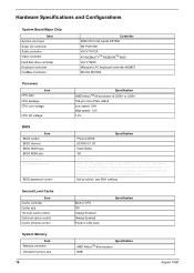
... CardBus Controller Controller ADM CPU+VIA Apollo K8T800 NS PC87392 VIA VT1612A ATI MOBILITYTM RADEONTM 9600 VIA VT8235 Mitsubish LPC keyboard controller M38857 RICOH R5C554 Processor CPU type Item CPU package CPU core voltage CPU I/O voltage Specification AMD AthlonTM 64 processor at 3000+ or 3200+ 754-... 1M Always Enabled Always Enabled Fixed-in write back Specification System Memory Item Memory controller Onboard memory size 18 Specification AMD AthlonTM 64 processor 0MB Aspire 1500
... CardBus Controller Controller ADM CPU+VIA Apollo K8T800 NS PC87392 VIA VT1612A ATI MOBILITYTM RADEONTM 9600 VIA VT8235 Mitsubish LPC keyboard controller M38857 RICOH R5C554 Processor CPU type Item CPU package CPU core voltage CPU I/O voltage Specification AMD AthlonTM 64 processor at 3000+ or 3200+ 754-... 1M Always Enabled Always Enabled Fixed-in write back Specification System Memory Item Memory controller Onboard memory size 18 Specification AMD AthlonTM 64 processor 0MB Aspire 1500
Aspire 1500 Service Guide
Page 32
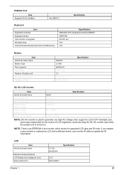
PCMCIA Port Item Supports 32 bit CardBus Yes (IRQ17) Specification Keyboard Item Keyboard controller Keyboard vendor Total number of LCD brightness. key Yes Yes Battery Item Vendor & model name Battery Type Pack capacity Cell voltage Number of battery cell Package ... with a different brand, use Inverter ID utility to LCD CCFT backlight user, and is also responsible for the control of keypads Windows keys Internal & external keyboard work simultaneously Specification Mitsubishi LPC keyboard controller M38857 DARFON 84-/85-
PCMCIA Port Item Supports 32 bit CardBus Yes (IRQ17) Specification Keyboard Item Keyboard controller Keyboard vendor Total number of LCD brightness. key Yes Yes Battery Item Vendor & model name Battery Type Pack capacity Cell voltage Number of battery cell Package ... with a different brand, use Inverter ID utility to LCD CCFT backlight user, and is also responsible for the control of keypads Windows keys Internal & external keyboard work simultaneously Specification Mitsubishi LPC keyboard controller M38857 DARFON 84-/85-
Aspire 1500 Service Guide
Page 33
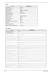
... Contrast control Brightness (cd/m sq.) Contrast Ratio Response Time (ms) (at contact discharge) 3000Vac 0.25 mA max. (@ 254Vac, 60Hz) 24 Aspire 1500 It should provide an efficiency of 80% minimum, when measured at maximum load under 115Vac. 19V 300mVp-pmax (20 MHz bandwidth) 0(min) 3.16A...) 8KV (at 25 dec C) Backlight Electrical Specification Supply voltage for LCD display (V) Specification 0.2175 TFT SXGA+ (1400x1050) 262K 10/30/40/40 Keyboard hotkey None 150 250:1 50 1 CCFL 3.3 (typ.) AC Adapter Item Vendor & model name Input Requirements Maximum input current (A, @90Vac, full load...
... Contrast control Brightness (cd/m sq.) Contrast Ratio Response Time (ms) (at contact discharge) 3000Vac 0.25 mA max. (@ 254Vac, 60Hz) 24 Aspire 1500 It should provide an efficiency of 80% minimum, when measured at maximum load under 115Vac. 19V 300mVp-pmax (20 MHz bandwidth) 0(min) 3.16A...) 8KV (at 25 dec C) Backlight Electrical Specification Supply voltage for LCD display (V) Specification 0.2175 TFT SXGA+ (1400x1050) 262K 10/30/40/40 Keyboard hotkey None 150 250:1 50 1 CCFL 3.3 (typ.) AC Adapter Item Vendor & model name Input Requirements Maximum input current (A, @90Vac, full load...
Aspire 1500 Service Guide
Page 34
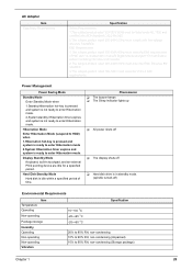
... FCC Certification before marketing into USA and Canada. 2.The subject product rated 200-240V 50Hz must meet the EMI requirements of time. Display Standby Mode Keyboard, built-in standby mode. (spindle turned-off T Hard disk drive is idle within a specified period of FCC part 15, Subpart B for a specified period. Hibernation Mode...
... FCC Certification before marketing into USA and Canada. 2.The subject product rated 200-240V 50Hz must meet the EMI requirements of time. Display Standby Mode Keyboard, built-in standby mode. (spindle turned-off T Hard disk drive is idle within a specified period of FCC part 15, Subpart B for a specified period. Hibernation Mode...
Aspire 1500 Service Guide
Page 53
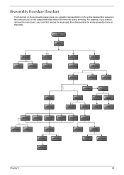
...if you want to remove the main board, you on the entire disassembly sequence and instructs you must first remove the keyboard, then disassemble the inside assembly frame in that need to be removed during servicing. Disassembly Procedure Flowchart The flowchart on ... on the components that order. Start Battery HDD Module *2 HDD HDD Holder *2 Dimm Cover Memory *1 Modem Cover *2 Modem Board Hinge Caps *2 Middle Cover Keyboard *6 LCD Module *2 Launch Board Lower Case Assembly *2 FDD Module *3 *3 *11 *4 RTC Battery *3 Mini PCI Card Plate Upper Case Assembly Disconnect Wireless...
...if you want to remove the main board, you on the entire disassembly sequence and instructs you must first remove the keyboard, then disassemble the inside assembly frame in that need to be removed during servicing. Disassembly Procedure Flowchart The flowchart on ... on the components that order. Start Battery HDD Module *2 HDD HDD Holder *2 Dimm Cover Memory *1 Modem Cover *2 Modem Board Hinge Caps *2 Middle Cover Keyboard *6 LCD Module *2 Launch Board Lower Case Assembly *2 FDD Module *3 *3 *11 *4 RTC Battery *3 Mini PCI Card Plate Upper Case Assembly Disconnect Wireless...
Aspire 1500 Service Guide
Page 66
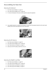
... pull out and upward to disconnect the keyboard cable from the main board carefully, then remove the keyboard from the main board. See "Removing the Middle Cover" on page 50.. 3. See "Removing the Middle Cover" on page 50.. 3. See "Removing...Removing the RTC Battery" on page 46.. 2. Use a plastic tweezers or a plastic flat screwdriver to expose the keyboard. 4. See "Removing the LCD Module" on page 50.. 3. Disassembling the Main Unit Removing the Keyboard 1. Disconnect the RTC battery cable then remove it. Removing the RTC Battery 1. See "Removing the Middle Cover"...
... pull out and upward to disconnect the keyboard cable from the main board carefully, then remove the keyboard from the main board. See "Removing the Middle Cover" on page 50.. 3. See "Removing the Middle Cover" on page 50.. 3. See "Removing...Removing the RTC Battery" on page 46.. 2. Use a plastic tweezers or a plastic flat screwdriver to expose the keyboard. 4. See "Removing the LCD Module" on page 50.. 3. Disassembling the Main Unit Removing the Keyboard 1. Disconnect the RTC battery cable then remove it. Removing the RTC Battery 1. See "Removing the Middle Cover"...
Aspire 1500 Service Guide
Page 67
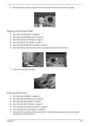
... cable then remove the four screws fastening the thermal module. 7. Then remove the CPU. See "Removing the Middle Cover" on page 51.. 4. See "Removing the Keyboard" on page 57.. 5. See "Removing the RTC Battery" on page 57.. 4. Lift up the CPU socket lever. See "Removing the RTC Battery" on page 57...
... cable then remove the four screws fastening the thermal module. 7. Then remove the CPU. See "Removing the Middle Cover" on page 51.. 4. See "Removing the Keyboard" on page 57.. 5. See "Removing the RTC Battery" on page 57.. 4. Lift up the CPU socket lever. See "Removing the RTC Battery" on page 57...

Aspire 1500 Service Guide
Page 68
... main unit and remove the 15 screws holding the lower case to the socket. See "Removing the Middle Cover" on page 57.. 4. See "Removing the Keyboard" on page 50.. 3. Disconnect the touchpad cable. 3. See "Removing the RTC Battery" on page 46.. 2. See "Removing the Battery" on page 57..... 59 Chapter 3 See "Removing the MimiPCI Card Plate" on page 58.. 7. See "Removing the Thermal Module" on page 57.. 6. See "Removing the Keyboard" on page 57.. 2. Lift up the CPU lever, then place the CPU back to the lower case. Installing the Processor 1. Remove the 6 screws that...
... main unit and remove the 15 screws holding the lower case to the socket. See "Removing the Middle Cover" on page 57.. 4. See "Removing the Keyboard" on page 50.. 3. Disconnect the touchpad cable. 3. See "Removing the RTC Battery" on page 46.. 2. See "Removing the Battery" on page 57..... 59 Chapter 3 See "Removing the MimiPCI Card Plate" on page 58.. 7. See "Removing the Thermal Module" on page 57.. 6. See "Removing the Keyboard" on page 57.. 2. Lift up the CPU lever, then place the CPU back to the lower case. Installing the Processor 1. Remove the 6 screws that...
Aspire 1500 Service Guide
Page 69
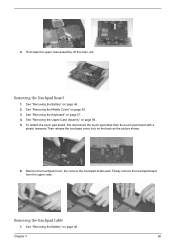
4. See "Removing the Keyboard" on page 50.. 3. To detach the touch pad board, first disconnect the touch pad cable from the upper case. Removing the Touchpad Cable 1. Removing the ...
4. See "Removing the Keyboard" on page 50.. 3. To detach the touch pad board, first disconnect the touch pad cable from the upper case. Removing the Touchpad Cable 1. Removing the ...
Aspire 1500 Service Guide
Page 70
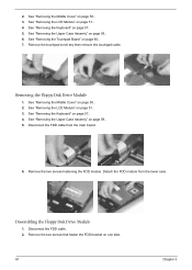
... FDD module from the main board. 6. Dissembling the Floppy Disk Drive Module 1. Disconnect the FDD cable from the lower case. See "Removing the Keyboard" on page 59.. 5. See "Removing the Upper Case Assemly" on page 57.. 4. Remove the two screws that fasten the FDD bracket on...on page 51.. 3. Removing the Floppy Disk Drive Module 1. Remove the two screws hastening the FDD module. Disconnect the FDD cable. 2. See "Removing the Keyboard" on page 50.. 3. See "Removing the Middle Cover" on page 57.. 5. See "Removing the Middle Cover" on page 51.. 4. See "Removing...
... FDD module from the main board. 6. Dissembling the Floppy Disk Drive Module 1. Disconnect the FDD cable from the lower case. See "Removing the Keyboard" on page 59.. 5. See "Removing the Upper Case Assemly" on page 57.. 4. Remove the two screws that fasten the FDD bracket on...on page 51.. 3. Removing the Floppy Disk Drive Module 1. Remove the two screws hastening the FDD module. Disconnect the FDD cable. 2. See "Removing the Keyboard" on page 50.. 3. See "Removing the Middle Cover" on page 57.. 5. See "Removing the Middle Cover" on page 51.. 4. See "Removing...

Aspire 1500 Service Guide
Page 71
... 46.. 2. See "Removing the Middle Cover" on page 57.. 4. Remove the screw that secure the VGA heatsink plate then remove the plate. See "Removing the Keyboard" on page 50.. 3. Remove the three screws that fastens the CPU heatsink plate then remove it. See "Removing the Battery" on page 57.. 4. 3. Then take...
... 46.. 2. See "Removing the Middle Cover" on page 57.. 4. Remove the screw that secure the VGA heatsink plate then remove the plate. See "Removing the Keyboard" on page 50.. 3. Remove the three screws that fastens the CPU heatsink plate then remove it. See "Removing the Battery" on page 57.. 4. 3. Then take...


